New Light

ChiefRunningPhist

Well-Known Member
Im not sure if the erythemal action spectrum (how much of what wavelength burns your skinn) can be exactly translated to a plant response. Skin and leaf is not the same. Also, @Randomblame was talking about having the right balance between uva and uvb. Apparently he had loss of yield with too much uvb.
But i still find it and intriguing approach....
Ya I thought that too, but I settled on the reasoning that there really is little difference between a qtr of a watt per m2 (10.6 UV index) vs an eighth of a watt per m2 (5.3 UV index), and that a plant will see somewhere in that range (well actually anywhere from 0.0mw/m2 -> 250mw/m2+) of UVB regardless what it does to humans. It's a way of obtaining a dosage range from observed and documented UV radiation. If you believe the plant grows best under the sun (me) then using the suns documented UVB doseage as a guidline might bring you closer to what the plant wants. I'd say ideally 1/4 watt of UVB radiation per m2 would be the max you'd want, and with a peak of 305nm - 310nm and a WV range from 285nm to 325nm.

I'm not sure what the correct ratio of UVA:UVB should be. It would be great to see some studies. I know when it comes to the sun that it's about a 95:5 UVA:UVB ratio, so I think as long as the UVB is present you really can't have too much UVA, but too little UVA for the UVB present could be an issue. I'm trying to go with 4× the UVA at least. Its nowhere near the 19:1 ratio of the sun though. Not that it matters, but I think the solacure bulbs look close to a 4:1 ratio, maybe 5:1...
yhst-139912697762728_2570_2226424.jpeg

I may find I need to add more UVA. Idk.. :confused:
 
Last edited:

ChiefRunningPhist

Well-Known Member
IIRC this is a 220 watt fixture? So you only need 224mw (at the wall) of uv to get a 10.6 uv index?
UV index deals with WV from 290-325nm only. So pretty much only UVB.

The UV index is based on a logarithmically weighted figure, which is then divided by 25.

So 25mw/m2 of logarithmically weighted UVB is equal to a UV index of 1. If you had 50mw/m2 of logarithmically weighted UVB then it is equal to a UV index of 2. If you had 100mw/m2 of logarithmically weighted UVB then it is equal to a UV index of 4. And so on and so on...


To calculate the logarithmically weighted figure the intensity readings of individual WV are multiplied by an "erythemal" percentage to determine its individual contribution to the entire logarithmically weighted figure. They do this for every WV from 290 - 325nm. Every WVs intensity has a certain "erythemal" % that it's multipled by/with, and then at the end they take all those multiplication totals and add them up to get the logarithmically weighted figure.

The logarithmic scale means that the closer you get to 290nm, the weight that each WVs intensity is given is increased exponentially. A 305nm WVs intensity is only worth 22% in the final logarithmically weighted figure. A 325nm WVs intensity is only worth 0.3% in the final logarithmically weighted figure. While a WVs intensity measurement at 290nm is worth 100% of its value in the final logarithmically weighted figure. The logarithmically weighted figure is a summation of the products of all the individual WV's intensities from 290 to 325 (290, 291, 292, 293, 294...) multiplied by their "erythemal" %'s.

If you look at this green line on the graph, you can see what "erythemal" % each WV is multipled by. You can see where they are finding the "290nm" on the X axis and where it matches with the "1.0" on the Y axis, also the "305" at "0.22", and the "325" at "0.003." The Y axis is based on a logarithmic scale, it doesn't go from 1 to 2 to 3 (linear), ... it goes from 1 to 100 to 1000 (logarithmic),... or 1.0 to 0.1 to 0.01 to 0.001 (logarithmic)...
1556166298031.png

A quick peek at the differences between linear and logarithmic..
linear_log.jpg
 
Last edited:

whytewidow

Well-Known Member
I seen a chart the other day really helping explain the differences in cri. Alot people dont understand cri. But alot people dont order certain strips bc of low cri. The 4000k 80cri and the 3500k 90cri were almost identical on the par curve map. Which I thought was cool. And they almost put out the same spectrum. I should've saved it. I'll see if I can find it. It showed the differences on 2700k 80cri and 3000k 90cri I think. And a few others.
 

SSGrower

Well-Known Member
UV index deals with WV from 290-325nm only. So pretty much only UVB.

The UV index is based on a logarithmically weighted figure, which is then divided by 25.

So 25mw/m2 of logarithmically weighted UVB is equal to a UV index of 1. If you had 50mw/m2 of logarithmically weighted UVB then it is equal to a UV index of 2. If you had 100mw/m2 of logarithmically weighted UVB then it is equal to a UV index of 4. And so on and so on...


To calculate the logarithmically weighted figure the intensity readings of individual WV are multiplied by an "erythemal" percentage to determine its individual contribution to the entire logarithmically weighted figure. They do this for every WV from 290 - 325nm. Every WV has a certain "erythemal" % that it's multipled by, and then at the end they take all those multiplication totals and add them up to get the logarithmically weighted figure.

The logarithmic scale means that the closer you get to 290nm the more weight that WVs intensity will have in the final logarithmic weighted figure. A 305nm WVs intensity is only worth 22% in the final logarithmically weighted figure. A 325nm WVs intensity is only worth 0.3% in the final logarithmically weighted figure. While a WVs intensity measurement at 290nm is worth 100% of its value in the final logarithmically weighted figure. The logarithmically weighted figure will be a summation of the products of all the individual WV's intensities from 290 to 325 (290, 291, 292, 293, 294...) multiplied by their "erythemal" %'s.

If you look at this green line on the graph, you can see what "erythemal" % each WV is multipled by. You can see where they are finding the "290nm" on the X axis and where it matches with the "1.0" on the Y axis, also the "305" at "0.22", and the "325" at "0.003." The Y axis is based on a logarithmic scale, it doesn't go from 1 to 2 to 3 (linear), ... it goes from 1 to 100 to 1000 (logarithmic),... or 1.0 to 0.1 to 0.01 to 0.001 (logarithmic)...
View attachment 4323370

A quick peek at the differences between linear and logarithmic..
View attachment 4323378
Sorry to do this to ya, but I know.
Should have been more targeted in my question.
But based on your answer I gather you havent fully figured out what you'll be using for wavelengths or chip effeciencies. I thought you had alread done that and were reporting 224mw (at the wall) is what you were going to use.

:peace:
 

ChiefRunningPhist

Well-Known Member
Sorry to do this to ya, but I know.
Should have been more targeted in my question.
But based on your answer I gather you havent fully figured out what you'll be using for wavelengths or chip effeciencies. I thought you had alread done that and were reporting 224mw (at the wall) is what you were going to use.

:peace:
Ya still looking at possible contenders as far as UV chips. The chip I am looking at has an output range from 2mw - 5mw. They operate @ 40mA and between 5v - 8v. So I extrapolated electrical requirements of 5.6v @ 40mA for .224w per chip. I extrapolated an output of 2.8mw at that power consumption. So 2.8/224 = .0125 or 1.25%. That's where I was coming up with my chip effeciency and output.
Screenshot_2019-04-25-15-22-53~2.png Screenshot_2019-04-25-15-23-28~2.png

EDIT:
Idk why I keep making these stupid little errors, but I had the mw range from 2mw-6mw in a previous calculation, instead of 2mw-5mw. The "7 UVB chip" figure is based of an average emission of 4mw per chip (halfway between 2mw - 6mw). If using 2.8mw it'd take ~10 UVB chips to achieve the UVB intensity in the WV range from 290-305, for an ~ equivalent UV index of 10.6.
 
Last edited:

ChiefRunningPhist

Well-Known Member
Like what @Rocket Soul said, I think the eryethmal curve is not good to judge off of. After writing a few posts I've allowed it to digest a bit and can see how flawed the index is at when calculating plant needs.

The biggest piece of useable data in the "thoughts on UV" post is the Wikipedia blurb about an average midday summer stating some arbitrary values.

0.6mw @ 290nm, 74mw @ 305nm, and the 478mw @ 325nm.

The 325nm intensity is only 0.3% of a factor to humans and sunburn, but also is 6.5× more intense than the 305nm reading. The plant might want 325nm, so calculating based on how sunburn you get isn't smart :wall:

Looks like I'll be doing more analysis.

Leaving out 325nm - 365nm may not be a good thing.
 

ChiefRunningPhist

Well-Known Member
Interesting idea to use the Peltiers.

What's the life expectancy on the UVB chips?
As far as UVB chips I've seen anywhere from 1000hrs to 6500hrs+.

Peltiers just don't have what it takes to cool water down efficiently enough. The amount of electricity needed is just way too high compared to a compressor.
Talking about the "seebeck" effect. Generating electricity from the waste heat.
 

ChiefRunningPhist

Well-Known Member
Looks like hgl's peltier thread was deleted?
Waiting for epoxy to cure and do a bit of soldering, and I'll be running this today.
View attachment 4330497
Ya I saw that too, I had a nice post about using a multi meter that got deleted lol oh well.

Anyways, your measurements are anywhere from 0.4w - 0.5w, so you could most likely run (1) 1/2watt of UV per Peltier. Idk how many COBs you run, but it might be enough to notice a difference.

EM radiation is absorbed really well when lower than 305nm. So you need very little to see an effect at that WV. Id make small UVB boards/stars and use the Peltiers to power the UVB stars. 40w/ft2 seems about right for COB growing. And by my estimations you'd only need about 5mW-7mW/ft2 of 305nm to have a high UV effect, or have the same 305nm doseage as a 10.6 UV index day. The chips I've been looking at peak at 310nm and if you ran (4), you'd consume 0.44w and output 4.8mW, and if each COB were for 1ft2 or at 40w/ft2 then each ft2 would also have 4.8mW/ft2 of 310nm being run by the Peltier. A 10.6 UV index day is about 7mw/ft2 in 305nm but mostly only at noon. I think 12hrs of a bit less intensity, and a bit higher WV will be enough to notice an effect. Im shooting for 6mW of 310nm per ft2, idk what the outcome will be. I may add a single UVC chip with peak of 280nm but not sure. Only 0.05mw/ft2 of 290nm is responsible for its role in a 10.6 UV index, so I'm just trying not to add much of it, but the lower in WV you go the more bang you get because the absorption is so much higher.

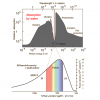
Look at how fast the rate of absorption increases from visible light to UV, it really picks up after 300nm, so the farther UV you go the less you need because it gets absorbed so much better, here's an example of water...
1556838938898.png

Some plant processes are NOT WV intensity dependepent. Ie, as long as the WV is there is all that matters, the intensity does nothing in changing the biochemical pathway. Idk what intensities are needed but just expanding the SPD may improve yield regardless of intensity.
 

SSGrower

Well-Known Member
Ya I saw that too, I had a nice post about using a multi meter that got deleted lol oh well.

Anyways, your measurements are anywhere from 0.4w - 0.5w, so you could most likely run (1) 1/2watt of UV per Peltier. Idk how many COBs you run, but it might be enough to notice a difference.

EM radiation is absorbed really well when lower than 305nm. So you need very little to see an effect at that WV. Id make small UVB boards/stars and use the Peltiers to power the UVB stars. 40w/ft2 seems about right for COB growing. And by my estimations you'd only need about 5mW-7mW/ft2 of 305nm to have a high UV effect, or have the same 305nm doseage as a 10.6 UV index day. The chips I've been looking at peak at 310nm and if you ran (4), you'd consume 0.44w and output 4.8mW, and if each COB were for 1ft2 or at 40w/ft2 then each ft2 would also have 4.8mW/ft2 of 310nm being run by the Peltier. A 10.6 UV index day is about 7mw/ft2 in 305nm but mostly only at noon. I think 12hrs of a bit less intensity, and a bit higher WV will be enough to notice an effect. Im shooting for 6mW of 310nm per ft2, idk what the outcome will be. I may add a single UVC chip with peak of 280nm but not sure. Only 0.05mw/ft2 of 290nm is responsible for its role in a 10.6 UV index, so I'm just trying not to add much of it, but the lower in WV you go the more bang you get because the absorption is so much higher.

Look at how fast the rate of absorption increases from visible light to UV, it really picks up after 300nm, so the farther UV you go the less you need because it gets absorbed so much better, here's an example of water...
View attachment 4330535

Some plant processes are NOT WV intensity dependepent. Ie, as long as the WV is there is all that matters, the intensity does nothing in changing the biochemical pathway. Idk what intensities are needed but just expanding the SPD may improve yield regardless of intensity.
I haven't been able to find a 310nm source, just 278 and 280 one is ina 3.5mm x 3.5mm format, the other is 6 x 6 both are SMD. Not havin a capacity to do reflow, but I'm gueasing if I can find the right board I can just put the led face down and heat the back side of the board?

Turned up to 50w got 2.6V 337mA at 60W got 3.25V and blew my miltimeter.

Couldn't figure out why I wasnt getting a reading on the 10A side...
Now I know it was blown previously. On hold for fuses.

Perhaps you could repost the multimeter tutorial in the meantime?
 

ChiefRunningPhist

Well-Known Member
Meauring current is done with the multimeter in series, measuring voltage can be easily measured by just using the probes to touch the "+" and "-" sides of the cct in parallel, current, is not that way. You also need to test the current with the load, not just an open ended power source. V = IR, or I = V/R.
USER_SCOPED_TEMP_DATA_orca-image-1421709145.jpeg_1556860739801.jpeg
Just move the red positive probe from middle to 10A, depending on the max measurement you anticipate.

Example:

Voltage is 3v. V=IR, or I=V/R, or (I) = (3v)/(R)

R=1.0, I=3A
R=0.1, I=30A
R=0.01, I=300A
R=0.001, I=3000A
...
Ect, ect
...
R=0.000001, I=3,000,000A
...
R is getting smaller and smaller
...
Finally R gets to actual "0"
...
R=0, I=infinity

So you have to have some resistance when you measure current, or you have to have your cct load in series when you measure. You can measure max driver current output, but if you tried a battery, it doesn't have a current limiting POT or mechanism, even a AA and you'd probably blow your multimeter.


They have devices that can measure current easily that use an inductor shaped like a clip. It kind of looks like a fat carabiner, with a trigger opening latch mechanism, but any current traveling through the wires that the device is clipped around can be measured without having to break the cct and wire the meter in series like normal, otherwise, ya, you have to break the cct and wire the multimeter in series.

EDIT:
41y84LoGMyL._AC_SY400_.jpg
 
Last edited:

ChiefRunningPhist

Well-Known Member
I haven't been able to find a 310nm source, just 278 and 280 one is ina 3.5mm x 3.5mm format, the other is 6 x 6 both are SMD. Not havin a capacity to do reflow, but I'm gueasing if I can find the right board I can just put the led face down and heat the back side of the board?

Turned up to 50w got 2.6V 337mA at 60W got 3.25V and blew my miltimeter.

Couldn't figure out why I wasnt getting a reading on the 10A side...
Now I know it was blown previously. On hold for fuses.

Perhaps you could repost the multimeter tutorial in the meantime?
Making little PCB's is easy. You can literally use a sharpie to draw your cct traces.

You just buy some copper clad laminate, then draw where you want your wires/traces on the board to be with a sharpie, then soak the little board in etchant (I'm using HCl + H2O2) and when you retrieve it from its chemical bath the only copper remaining will be the copper under the sharpie marker. You use a bit of acetone or nail polish remover to get rid of the permanent marker to reveal the Cu underneath. Then just add a bit of solder paste to the chip locations on the board, and then stick your chips ontop of the solder paste. Then throw it in your household oven or use a toaster oven to flow the solder paste.

There's tutorials online on how to do it easily. The chips will be placed ontop of the sharpie/Cu trace line, so make sure to draw your traces so the chip will sit ontop of them, if you only draw the line up to the edge of the chip then you won't be able to make the proper connection. The chip terminal pads are underneath and separated by only a small distance.

I'm using a Eagle to design the cct and print the black lines onto the PCB because I'll have lots of traces and lots of chips ect. I'm also getting a stencil cut so that I can apply solder paste easily and just to the places that need it. ... But...with a 1- 5 chip PCB, just drawing the lines is a lot easier then creating a Gerber file and getting stencils cut and bla bla bla You can buy 6" squares of PCB for like $5 and you can cut them to any size you need.
 
Last edited:
Top