You are using an out of date browser. It may not display this or other websites correctly.
You should upgrade or use an alternative browser.
You should upgrade or use an alternative browser.
On/Off functin for meanwell HLG style drivers using dimming and arduino
- Thread starter VegasWinner
- Start date

VegasWinner
Well-Known Member
The system is scaleable. I can connect many of these 16 channels drivers for a total of 900 channels. Running a 25 pair cat 5 cable for 5 volts is not much. I have run plenty of phone and computer cable cat 5, wall mounted just fine. When you have wireless, others have access to your system and/or know of your systems locations and existence. Some people may not want that type of attention for a smartphone app. perhaps when growing is legal in all 50 states you can go WiFi and Internet. I know of many companies that run their greenhouse from the internet.I have contemplating how to build in scalability into my lights so I don't have to do a major overhaul to control them later. In the end I will have 18 individual light units to cover the room, so I would need more than 16 channels, and that's a lot wire running around the room. Really like the idea of individual wireless controllers in each light controlled by a master controller, but that won't be cheap; maybe for the high end user. Or maybe a local wireless unit that controls 4 light units via cables, a comprise. Just thoughts for now, I will monitor progress, and help out where I can. I am couple of months away from starting the automation project.
Keep up the good work.
VegasWinner
Well-Known Member
For my own personal use I have an arduino Mega2560 with plenty of pins available. I also use a 20x4 lcd screen and I am setting up a custom button controller. I also have the internet shield and considering the WiFi shield, as well. I have not investigated the WiFi shield, but I imagine it will do the same as a Rasberry Pi, running Unix, which I used to run my office on Linux servers and Windows back end. secure network. I will look inot the WiFi optin for those interested in WiFi and smartphone apps. They are available under arduino. peace
VegasWinner
Well-Known Member
Our Adafruit Bluefruit LE (Bluetooth Smart, Bluetooth Low Energy, Bluetooth 4.0) nRF8001 Breakout allows you to establish an easy to use wireless link between your Arduino and any compatible iOS or Android (4.3+) device. It works by simulating a UART device beneath the surface, sending ASCII data back and forth between the devices, letting you decide what data to send and what to do with it on either end of the connection.
Unlike classic Bluetooth, BLE has no big contracts to sign and no major hoops that you have to jump through to create iOS peripherals that you can legally design and distribute in the App Store, which makes it a great choice compared to classic Bluetooth which had (and still has) a lot of restrictions around it on the iOS platform.
And now that Android also officially supports Bluetooth Low Energy (as of Android 4.3), it's also -- finally! -- a universal communication channel covering the main mobile operating systems people are using today.
https://www.adafruit.com/product/1697
Vegas
MrTwist1
Well-Known Member
I personally think wifi and a smartphone app would be very useful.For my own personal use I have an arduino Mega2560 with plenty of pins available. I also use a 20x4 lcd screen and I am setting up a custom button controller. I also have the internet shield and considering the WiFi shield, as well. I have not investigated the WiFi shield, but I imagine it will do the same as a Rasberry Pi, running Unix, which I used to run my office on Linux servers and Windows back end. secure network. I will look inot the WiFi optin for those interested in WiFi and smartphone apps. They are available under arduino. peace
qballizhere
Well-Known Member
What sensor are you going to use? If its http://www.co2meter.com/collections/co2-sensors/products/k-30-co2-sensor-moduleI will need assistance form those folks ujsing CO2 and PI or arduino to work out the CO2. Vegas
Here is some code for the sensor i was going to try. https://www.openhomeautomation.net/wireless-co2-sensor-arduino/
Have you thought about the idea of a custom pcb with the components on it you want? Instead of piecing together different parts?
qballizhere
Well-Known Member
You really want to go all out you can get https://www.sparkfun.com/products/1...ail&utm_term=0_fa5287abaf-833a56f2a2-62773297 not just have a watering system but you dont even have to mix the nutes!
VegasWinner
Well-Known Member
What sensor are you going to use? If its http://www.co2meter.com/collections/co2-sensors/products/k-30-co2-sensor-module
Here is some code for the sensor i was going to try. https://www.openhomeautomation.net/wireless-co2-sensor-arduino/
Have you thought about the idea of a custom pcb with the components on it you want? Instead of piecing together different parts?
I am looking to keep cost down. Working on off the shelf components. right now all the components works together, I just have to package it for appearances. I am focusing on coding right now. peace.
[/B][B said:two of the outlets are always on... i would read the fucking manual
I don't need to read any FUCKING manual. I just use shit and make it work. I was taught if you have nothing nice to say, STFU. You been picking on me since I got here. That is called a BULLY. Enjoy yourself. I have shit to do, and it does not include you. You are the second asshole I have met here. congratulations. I am going to ignore you from here on in. have a great life, and leave me the fuck alone. peace get a life with me not in it.
VegasWinner
VegasWinner
Well-Known Member
I am going to ignore the trolls and continue. I am sorry for the outburst, but I detest ignorance and disrespect. I am a former marine from Vietnam and I do not play well with others. In fact my ex-wife wanted to buy me a T-shirt that says that. I told her I do not advertise and people will have to learn the hard way. Two people just learned that here.
I ride my HD, motorcycles; hard and don't play. I build my HD's and do it to my own sense of what i like. I do everything that way. I am going to build and develop the GrowGreen Contoller, because there is a need for it and there is no product meeting that need. I want to give back to the community in this way. Trolls will not stop me.
I am awaiting for batteries for the RTC, and the 16 channels pwm driver. it seems the PWM driver wants the same two pins A4 and A5 for the i2c buss along with the lcd driver and rtc. I am going to have to use a pullup resister to connect multiple devices to the same physical pins using a breadboard. sigh. I believe it will have to be a 1k ohm resister to keep everyone happy.
The smaller controller, 4 led PWM signals and 2 Recycle timers channels is adequate for most. I find I need 6 led drivers and 1 recycle circuit. I have been researching and I can transform analog and digital p8ins to output for pwm needs if necessary. So the smaller unit does not need to share A4 and A5, because there is an additional pin circuit for the RTC module. Now just a matter of packaging the unit. Te lcd shield does not cover up the SCL and SCA pins, so many lcd drivers can work.
It is the larger unit that will need some thinking out of the box. But I can connect up to 900 PWM driver circuits, so I know it is possible.
I am working on the logic code for the menu system now. decided to develop my own as I am not happy with the overhead of the menu system libraries developed so far.
Onward and Upward.
Happy Father's Day to you Dad's out there. My ex-wife took the family and children and turned them against me, so I can not celebrate Father's Day anymore. Reminds me of the Trolls I find here, just like my ex-wife. BULLY's. peace
VegasWinner
Well-Known Member
You have seen the prototype. I like it, for cost and size. It has basic components that can be all connected together with the shield attached to the arduino. Easy. looks nice and the RTC is mounted adjacent to the arduino. The Humidity/temp sensor is mounted in the control space. The basic unit consists of the following:
1 arduino uno $25.00 - >https://www.adafruit.com/products/50
1 lcd shield $12.00 ->http://www.robotshop.com/en/16x2-lc...ZIkc2aDh1lliF6l2tDXicIyTK-AlRyjc5RxoCnETw_wcB
or this lcd shield -> https://www.adafruit.com/products/716
1 RTC module $15.00 -> https://www.sparkfun.com/products/12708
1 temperature/humidity sensor $10.00 ->https://www.sparkfun.com/products/10167 DHT11 or DHT22 cost is not much different in the two. code is the same
2 outlets controlled by GrowGreen Controller $40.00 9 (currently out of stock). I have two running right now for 2 weeks doing fine. this is the critical component, as it allows control over the light circuit through PWM signal, and it has warranty and testing.. -> https://www.adafruit.com/products/2935
total cost is $102 plus S&H $20, plus sketch supplied by me, FREE total cost - $122. For a larger system you have to add the 16 channel PWM controller $15.00/ea ->https://www.adafruit.com/products/815 for a total of six max.
I would recommend using one controllable outlet for each fixture, $20/ea plus S&H keeping total watts under 400w; two drivers; when possible to lower inrush current issues. You can run two drivers with separate power wiring to each outlet allowing for ramp up of 30-60 seconds reducing inrush current and creating a daily spike for usage rates in power. if you have a large number of lights, turning them on in series is better, but most have a timer on their breaker panel starting all those lights at once like a commercial building. Better to let them ramp up one after another, reducing current inrush and spreading current demand over a few minutes.
Commercial GrowGreen Controller would be 6-16channel pwm drivers for a total cost of just over $225. Not bad to control a bunch of lights from one location. if you want to have WiFi control there is a module for that with a smartphone app as well. Easy to program, like your DVD player. lol.
I have shared the code for the DHT11 and both LCD screens. One has a rotary encoder and the other has buttons. I am liking buttons more, when I thought I would not and wanted a rotary encoder. I will share the sketch for the arduino GrowGreen Controller, as well.
For myself I am using the following:
1. Arduino Mega 2560 $45, 20x4 LCD with a i2c controller card, an analog thumb joystick with select button, an RTC module, and a DHT11. I need to control six light circuits and one recycle circuit. peace
Vegas
VegasWinner
Well-Known Member
What sensor are you going to use? If its http://www.co2meter.com/collections/co2-sensors/products/k-30-co2-sensor-module
Here is some code for the sensor i was going to try. https://www.openhomeautomation.net/wireless-co2-sensor-arduino/
Have you thought about the idea of a custom pcb with the components on it you want? Instead of piecing together different parts?
That is a nice setup. The code looks easy enough. perhaps i can work with someone that already has the unit up and running and willing to share the sketch code for others to use. I see two things getting the current level, and controlling the tank through the valve with a micro-controller, 12v usually. For those that are doing this, they can share and we can build it into the framework. I already set aside a menu for sensors like these in the system.
Vegas
VegasWinner
Well-Known Member
For those needing more PWM circuits, the Arduino Mega2560 has 8 additional PWM pins available, along with the original A0-A5 pins on the Uno, there are the A6-A15 pins available, before getting the 16 channel PWM board. You can access these pins with the LCD shield fully attached. The RTC can be attached and the DHT11 can al;so be connected with the lcd shield attached fully. The Arduino Mega2560 goes for about $45 $20 more than the Uno. I plan on using the Mega2560 myself.
I have been working on a menu system. I have put a placard holder for CO2 sensors. I figure there are guys here using them, and they can send me the code to include for operation and control of the CO2 cylinder. peace
I have been working on a menu system. I have put a placard holder for CO2 sensors. I figure there are guys here using them, and they can send me the code to include for operation and control of the CO2 cylinder. peace
VegasWinner
Well-Known Member
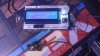
Time for another update. I have a picture of the ArduinoMega2560 running the basic code set now. The sketch is running the main menu system and gathers date, tine, temperature and humidity as the main screen. menu's are accessed through hitting the select button, i.e. push the button vice left,right, up, down. The current has the R$TC clock chip up and running along with the DHT11 temp/humidity sensor running, as well.
I have attached a picture of the GrowGreen LED Controller with the proposed lcd screen shield and arduino meg2560. enjoy
Vegas
I have attached a picture of the GrowGreen LED Controller with the proposed lcd screen shield and arduino meg2560. enjoy
Vegas
Attachments
VegasWinner
Well-Known Member
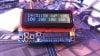
Update:
I have completed the coding/sketch and I have a running unit. The Controller drives six channels using PWM pins 3,4,5,9,10,11. The display show four channels because the lcd is not bigger. It also shows time, temperature, humidity, and with the up button calls up the menu to set the times and brightness of each channel.
part list:
Arduino Uno Rev 3 ->https://www.adafruit.com/products/50
i2c RGB lcd shield by adafruit. ->https://www.adafruit.com/products/715
DS1307 Real time Clock ->https://www.adafruit.com/products/264
DHT11 Temperature/humidity Sensor ->https://www.adafruit.com/products/386
Breadboard ->https://www.adafruit.com/products/65
and the sketch GrowGreen.ino can be found here ->https://github.com/AvidLerner/GrowGreen
peace
I have completed the coding/sketch and I have a running unit. The Controller drives six channels using PWM pins 3,4,5,9,10,11. The display show four channels because the lcd is not bigger.
part list:
Arduino Uno Rev 3 ->https://www.adafruit.com/products/50
i2c RGB lcd shield by adafruit. ->https://www.adafruit.com/products/715
DS1307 Real time Clock ->https://www.adafruit.com/products/264
DHT11 Temperature/humidity Sensor ->https://www.adafruit.com/products/386
Breadboard ->https://www.adafruit.com/products/65
and the sketch GrowGreen.ino can be found here ->https://github.com/AvidLerner/GrowGreen
peace
Attachments
Last edited:
Organic Miner
Well-Known Member
Sweet!Update:
I have completed the coding/sketch and I have a running unit. The Controller drives six channels using PWM pins 3,4,5,9,10,11. The display show four channels because the lcd is not bigger.
part list:
Arduino Uno Rev 3 ->https://www.adafruit.com/products/50
i2c RGB lcd shield by adafruit. ->https://www.adafruit.com/products/715
DS1307 Real time Clock ->https://www.adafruit.com/products/264
DHT11 Temperature/humidity Sensor ->https://www.adafruit.com/products/386
Breadboard ->https://www.adafruit.com/products/65
and the sketch GrowGreen.ino can be found here ->https://github.com/AvidLerner/GrowGreen
peace
VegasWinner
Well-Known Member
I forgot to add the output pins are PWM pins 3,4,5,9,10,11, and require a six pin connector with the PWM output tied to one leg and ground common tied to the other legs. you also need the outlet controller by adafruit for each fixture you want to turn on and off s well as dim -> they can be found only here right now -> https://www.adafruit.com/products/2935
you will also need solder iron and tools, wire a breadboard like this one ->https://www.adafruit.com/products/64
allows for connecting power and ground from arduino and other devices can share the 5vdc and GND sources. A six pin double header tied back to pins 3,4,5,9,10,11, and bottom tied to common ground for all six pins, creating PWM circuits, and a project enclosure, which I am working on, as well. When I get the project packaged I will show and tell and be able to provide some DIY kits for others, either completely assembled, or parts to be assembled with instructional video. working out the details. I am also working on the larger module that will drive 22 PWM channels and beyond. An Arduino Mega2560 is need for that job. Code to follow for the beast that drives many 16 channel PWM boards. peace
Vegas
VegasWinner
Well-Known Member
I made some minor revisions to the sketch effecting channels five and six. posted on GitHub. I am working on a final package that includes a rotary switch with push button, a 20x4 lcd screen mounted in a Rasberry Pi container and a six channels connector to connect the PWM cabling, using an Arduino Uno Rev 3. Working on the button interface. The rest is completed, except housing it. pictures to follow. peace
VegasWinner
Well-Known Member
I am working on packaging the first unit, the Arduino Uno with the 16x2 lcd screen and five buttons, s the entry model. The GrowGreen CoB LED Controller has six output channels with VCC and GND pins with PWM. I am awaiting a few parts and i will be able to package the first unit for pictures and demo. it works fine. It will be the entry level model. I am working on the multi-channel model over six channels. peace
Vegas
Vegas
VegasWinner
Well-Known Member
latest update: I have completed the basic model the six channel PWM driver using the Arduino Uno, Rev 3. adafruit lcd button shield, DS1307 RTC, and a DHT11-optional. I am awaiting the case and some parts to package it together. i use mine on a sheet of plexiglass along with the LDD-6 Driver Board from Coralux, and the MW 48v power supply. I run cables using security cable; two wire; from the LDD driver board to the LED light dimmer circuit on the driver and the Relay switch, using a y tap for the five volt signal. I directly control the dimming and on/off capability of both CoB's and LED's. My settings are remembered even after power off. The clock resets itself to the current time it went offline and continues from there. if you spent hours offline, you will have to reset the time to the current time, but the cycles will continue as if there was no power outage.
I also have developed a twelve channel PWM driver using the exact same components. I have written two sketches for eth Arduino Uno rev 3. One is called the GrowGreen.ino and the other is called GrowGreen12Channel.ino. Both are available at this location on Github ->https://github.com/AvidLerner/GrowGreen If you buy the components as follows you can build either the six or twelve PWM channel unit as desired.:
1. Arduino Uno Rev 3 ->https://www.adafruit.com/products/50
2. Adafruit lcd shield using only pins 5v, GND, SDA, SCL ->https://www.adafruit.com/products/716
3. DS1307 RTC ->https://www.adafruit.com/products/264
4. a 12v power supply ->https://www.adafruit.com/products/798
5. LDD6up Driver ->http://coralux.net/?wpsc-product=ldd-6-driver-board
6. Mean Well LDD drivers 700mA & 1000mA. The 1000mA run the Royal blues and the 700mA run the various reds. One LDD driver for each 12 red or bluer leds, 15 max.
7. Mean Well SE-350-48v power supply ->http://www.meanwell.com/webapp/product/search.aspx?prod=se-350
8a. relay options a. -> adafruit built one for each fixture ->https://www.adafruit.com/products/2935
8b. relay option b sparkfun relay unit which can be connected with the driver at the fixture and connected to the GrowGreen Controller with extension cables->https://www.sparkfun.com/products/13815
9. PWM connectors from Arduino Uno to the case for connecting the six or twelve channels.
I will provide a video in the next week or so, showing the system and it's operation. until then have fun building your own unit. I will provide DIY kits with the code loaded, unit assembled, and tested.
As soon as I get the case in, I will provide a video for you folks. My setup is running two 200w LED lights, a Royal blue channel , Deep Red. IR channels and a Far Red channel at various times and lumen levels. 24/7 and I already went through a power outage and recovered. i just had to reset my clock after being offline for hours. peace
Vegas
Sativied
Well-Known Member
Nice job and thanks for sharing, I'm surprised this thread doesn't have hundreds of eager cob light growers all over it. The the ramp up/down option alone is worth it, something I expect will become default practice some day sooner than later. Not just for minutes or to avoid inrush, but boost to full intensity gradually during the first hours and start dimming hours before the end of the day, The start and end intensity should also be something like 20%, or a configurable min and max output setting. The best values would require testing for cannabis specifically but based on trials with other species the potential for additional energy savings is huge without negative effects. 15-20% is easily feasible.
I planned to dust off an arduino and build something myself inspired partly by a dutch cob grower but yours comes with display... It's probably not really functionally important in a good led light but in his setup it measures the temps of the cobs and shuts down the lights. Instead or additionally it could display the temp, or indicate with multi color diodes...

...or, in the ramp up/down scenario, it could be used to turn on fans only when needed, and as fast as needed, 5v vs 12v, or with that pwm the fans individually as needed. Not passive, not active, but "adaptive cooling".
I planned to dust off an arduino and build something myself inspired partly by a dutch cob grower but yours comes with display... It's probably not really functionally important in a good led light but in his setup it measures the temps of the cobs and shuts down the lights. Instead or additionally it could display the temp, or indicate with multi color diodes...
...or, in the ramp up/down scenario, it could be used to turn on fans only when needed, and as fast as needed, 5v vs 12v, or with that pwm the fans individually as needed. Not passive, not active, but "adaptive cooling".
Similar threads
- Replies
- 15
- Views
- 2K
- Replies
- 28
- Views
- 3K
- Replies
- 19
- Views
- 3K
- Replies
- 48
- Views
- 9K