LED Dim to OFF. 0-10V. Electronics Nerds. Get in here

MidnightSun72

Well-Known Member
Ok so Ive had this problem for about a year. LED drivers come in two flavours 0-10V dimming and 1-10V dimming. 0-10V let's you DIM to OFF meaning when the dimmers get 0V the light will actually turn right off. On the other hand, 1-10V dimmers can only dim to 10% output and thus stay on when you provide the dimmer wires 0V. When setting up bigger rooms this forces me to use big contactor relays to trigger all the lights on and off at once.

What I want to do is create a circuit with the logic being that if the voltage drop below 1V the relay should cut power to the fixture. Anything over 1V should = ON. That way as the % increases dimming proceeds as normal after 1V.

I've been looking at these octocouplers sith and low level triggers but I've never used a device like this and don't know what i am looking for totally. Additionally me and my cousin made up a circuit using a comparator. But I don't wanna have to make a whole PCB myself. I just wanna buy something that can be adapted fairly easily. And I want the unit cost to be under $6. Is this asking too much?

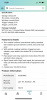
check this device out. I feel like it's close to being what I need.
XCSOURCE® 5PCS 5V 1 Channel Relay Shield Module optocoupler For PIC AVR DSP ARM Arduino TE213 https://www.amazon.ca/dp/B00ZR3B252/ref=cm_sw_r_cp_api_glt_i_6G00CAVWZTMR06DVCHME?_encoding=UTF8&psc=1


A04BD855-C293-43F6-802A-07F450F2967B.pngACAC3DF6-55A7-4FE2-92A7-3F87938EF453.png4AE90C2C-E8D0-4E14-8B3C-B28078EC4006.png
 

cobshopgrow

Well-Known Member
a cleaner aproach would be to use a microcontroller and switch the relais with it.
what you want to do maybe work to some degree.
these relais modules have a transistor or fet in front to drive the relais itself, i think most use a transistor.
so if you have a certain voltage or current on the in pin its open or closed.
it can easily be it wont switch when you want it, but you can give it a try, maybe try to get a better offer for less of these genereic cheap modules and try
you can limit the current with a resistor, or a potentiometer, simply in series with your in pin then.
well, its not really made for this usage but it could work out, can be fet or transisotr dont really go low as you apply still too much voltage or current (fet or transistor).
forgot to mention, there is also the risk even if you get it to of with a limiting resistor that on the other side youre not able to go fully on anymore.
there is lots to find how to drive a transistor, you prob get the idea.
 
Last edited:

MidnightSun72

Well-Known Member
a cleaner aproach would be to use a microcontroller and switch the relais with it.
what you want to do maybe work to some degree.
these relais modules have a transistor or fet in front to drive the relais itself, i think most use a transistor.
so if you have a certain voltage or current on the in pin its open or closed.
it can easily be it wont switch when you want it, but you can give it a try, maybe try to get a better offer for less of these genereic cheap modules and try
you can limit the current with a resistor, or a potentiometer, simply in series with your in pin then.
well, its not really made for this usage but it could work out, can be fet or transisotr dont really go low as you apply still too much voltage or current (fet or transistor).
forgot to mention, there is also the risk even if you get it to of with a limiting resistor that on the other side youre not able to go fully on anymore.
there is lots to find how to drive a transistor, you prob get the idea.
Are you saying I can just use the transistor instead of the whole opto coupler deal?
 

MidnightSun72

Well-Known Member
maybe better to search your amazon for " LM393 Comparator Module ", ive never used these, check the specs yourself but they apear more promissing for your plan.
Red Digital Window Voltage Comparator Overvoltage Undervoltage Protection Voltage Measurement Module 12V/24V(24V) https://www.amazon.ca/dp/B07NY8SGN8/ref=cm_sw_r_cp_api_glt_i_F6ACDZQKDNKV7RNXQ2NR

What do you think of this? It has a set button on it. Am I correct to assume that sets on the trigger voltage? It says it can sense 0-100V in 0.1V increments.
 

Rocket Soul

Well-Known Member
For what purpose do you wanna do this? It just seems like introducing another point which could fail in one of the most important pieces of automation.
In what scenario would you wanna turn off the relays with dimming? Im assuming the relays allready have a timer so you can set to 12/12 etc. So they switch on and off with no probs. In what scenario would you be in your grow during lights on and then have to turn off all the lights with dimming? Sorry, not meaning to be unreasonably questioning just curious on why you wanna do this. Maybe im missing something or making assumptions.

If i was to add this function to my grow i would:
-keep the relays with their standard timers, set for 12/12 for flower etc. Make sure main control for daily switching is "hard wired", no possibility to fail due to whatever dimmer problems could arise.
- Aquire 0-10V dimming drivers, and as such be able to turn the lights of thru dimming. Yes new drivers will cost you but so would this new solution. But switching the relays thru your dimmers may be inviting Murphy and his law for a visit.
 

cobshopgrow

Well-Known Member
Red Digital Window Voltage Comparator Overvoltage Undervoltage Protection Voltage Measurement Module 12V/24V(24V) https://www.amazon.ca/dp/B07NY8SGN8/ref=cm_sw_r_cp_api_glt_i_F6ACDZQKDNKV7RNXQ2NR

What do you think of this? It has a set button on it. Am I correct to assume that sets on the trigger voltage? It says it can sense 0-100V in 0.1V increments.
i had a look at this
there is also a single channel version, there are trim potentiometers where you should be able to set the limit, these relais always work 2 ways depends on how you wire them, normally closed or open.

think the unit you linked will do also, its just hard to decipher the description (also hard for the lm393 one) and what the 5 functions are, lol.
voltage measurement plus on off limits for the relay i see.

for PWM and optocoupler you would need a source for the PWM of course a MCU or a NE555 circuit.
 
Last edited:

cobshopgrow

Well-Known Member
For what purpose do you wanna do this? It just seems like introducing another point which could fail in one of the most important pieces of automation.
In what scenario would you wanna turn off the relays with dimming? Im assuming the relays allready have a timer so you can set to 12/12 etc. So they switch on and off with no probs. In what scenario would you be in your grow during lights on and then have to turn off all the lights with dimming? Sorry, not meaning to be unreasonably questioning just curious on why you wanna do this. Maybe im missing something or making assumptions.

If i was to add this function to my grow i would:
-keep the relays with their standard timers, set for 12/12 for flower etc. Make sure main control for daily switching is "hard wired", no possibility to fail due to whatever dimmer problems could arise.
- Aquire 0-10V dimming drivers, and as such be able to turn the lights of thru dimming. Yes new drivers will cost you but so would this new solution. But switching the relays thru your dimmers may be inviting Murphy and his law for a visit.
as far i got him hes is looking to switch at least a part of his power supplies on the DC side so the input caps of the drivers stay charged and dont cause the inrush current when switching several on at the same time.
of course he could start them with seperate timers a minute apart each, but seems thats a bit inconvenient.
 

MidnightSun72

Well-Known Member
For what purpose do you wanna do this? It just seems like introducing another point which could fail in one of the most important pieces of automation.
In what scenario would you wanna turn off the relays with dimming? Im assuming the relays allready have a timer so you can set to 12/12 etc. So they switch on and off with no probs. In what scenario would you be in your grow during lights on and then have to turn off all the lights with dimming? Sorry, not meaning to be unreasonably questioning just curious on why you wanna do this. Maybe im missing something or making assumptions.

If i was to add this function to my grow i would:
-keep the relays with their standard timers, set for 12/12 for flower etc. Make sure main control for daily switching is "hard wired", no possibility to fail due to whatever dimmer problems could arise.
- Aquire 0-10V dimming drivers, and as such be able to turn the lights of thru dimming. Yes new drivers will cost you but so would this new solution. But switching the relays thru your dimmers may be inviting Murphy and his law for a visit.
too late now because fixtures are built. But in future I will try to always get 0-10V. But that still leaves me like 75 drivers I gotta modify for 0-10V dimming. Lol

Right now I control my lights using a big contactor relay. It's not introducing any more failure points in my mind since I would just be moving the relay to be onboard each light. So when I control multiple lights it's just a matter of connecting the RJ11 telephone wire into my light and boom it's joined the system. No adding a timer or relay for the light.
The main reason for this is want my lights controllable from Gavita or Trolmaster light controllers so they work seamlessly when mixed into a room with lights already being controlled for this (for example with 1K DE fixtures that also use 0-10V). This eliminates having to put any timers on the lights etc. You just plug in your telephone line and that light joins the system on off and dim whenever the controller says. My situation right now I need to cut power to the lights separately by controlling the power to the lights on its own timer.

Coles notes: adding another light to a room already on 0-10V control means you gotta add it on a time controlled circuit VS just being hooked up to power snd the controller giving the light commands. For example in my room right now all the 220V is switched from 1 really. Which means if I want to add 730nm EOD then it needs to be on a seperate circuit vs just getting it's won timer etc. With each light dimming to 0 it simplifies my room as well as another project I am working on at the moment. Maybe you aren't growing with the same control systems. But for me it would really make my lights plug and play into any system.

all else failing my plan is just to embed 1 sonoff per light and then they will have their own internal timer relay, but IMO wouldn't be a slick as just dimming to off
 

MidnightSun72

Well-Known Member
as far i got him hes is looking to switch at least a part of his power supplies on the DC side so the input caps of the drivers stay charged and dont cause the inrush current when switching several on at the same time.
of course he could start them with seperate timers a minute apart each, but seems thats a bit inconvenient.
No I wanna control the AC side. So the driver is totally off. I also did think about controlling just the DC output of the driver but good luck finding a relay that control 285V DC in a reasonable size/price anything over 30VDC seems uncommon in my relay search. .

Also I ordered these to try out. They say they trigger at 3V. This would also be acceptable to me. Even 5V might be Ok. But basically anything under 30% would be off. Which is fine by me. The lowest I've had to dim to is 38% so I can live with a 30% to 100% dimming range with anything under 30% being off.
 
Last edited:

cobshopgrow

Well-Known Member
true these cheap relais arent really good perfroming on DC.
how do you reenable them, when you dim below 1V the relais goes off and then?? turning the dial up again wont turn it on again.
hard to say how your 3V relais will behave.
edit .solved
 
Last edited:

Rocket Soul

Well-Known Member
too late now because fixtures are built. But in future I will try to always get 0-10V. But that still leaves me like 75 drivers I gotta modify for 0-10V dimming. Lol

Right now I control my lights using a big contactor relay. It's not introducing any more failure points in my mind since I would just be moving the relay to be onboard each light. So when I control multiple lights it's just a matter of connecting the RJ11 telephone wire into my light and boom it's joined the system. No adding a timer or relay for the light.
The main reason for this is want my lights controllable from Gavita or Trolmaster light controllers so they work seamlessly when mixed into a room with lights already being controlled for this (for example with 1K DE fixtures that also use 0-10V). This eliminates having to put any timers on the lights etc. You just plug in your telephone line and that light joins the system on off and dim whenever the controller says. My situation right now I need to cut power to the lights separately by controlling the power to the lights on its own timer.

Coles notes: adding another light to a room already on 0-10V control means you gotta add it on a time controlled circuit VS just being hooked up to power snd the controller giving the light commands. For example in my room right now all the 220V is switched from 1 really. Which means if I want to add 730nm EOD then it needs to be on a seperate circuit vs just getting it's won timer etc. With each light dimming to 0 it simplifies my room as well as another project I am working on at the moment. Maybe you aren't growing with the same control systems. But for me it would really make my lights plug and play into any system.

all else failing my plan is just to embed 1 sonoff per light and then they will have their own internal timer relay, but IMO wouldn't be a slick as just dimming to off
Didnt realize it was so many, thats alot of grow. Do you have it logged here or anywhere? Thats some serious growporn.

I dont know how to do what you want, when it comes to these things ledgardener seems to have a tight setup with lots of diy/rasberry/automation. Not sure if it will help but maybe you can find somethig.
 

cobshopgrow

Well-Known Member
may try the PWM route.
it says its PWM, while could be everything.
with luck its something generating a PWM signal, basically like the microcontroller optocoupler aproach which seems to be the cleanest in my eyes anyway.
....realized youre using a 0-10V dim system allready.
 
Last edited:

Rocket Soul

Well-Known Member
may try the PWM route.
it says its PWM, while could be everything.
with luck its something generating a PWM signal, basically like the microcontroller optocoupler aproach which seems to be the cleanest in my eyes anyway.
....realized youre using a 0-10V dim system allready.
This could be it. Also. If you search the forum theres a lot of info in the 3 in 1 led dimming thread. Be patient though, iirc theres like 5-10 pages of various arguing with Vegaswinner.
 
Top