LED Driver Amperage question

Bretton Lutz

New Member
I have a cheap LED driver bought off ebay to run 20 watt LED's (also bought off ebay). Trying to see whats happening with them. The voltage is stamped 20-38 V and 600 mA. I wanted to see if the driver could run two LEDS so I hooked it up and measured the amperage on one LED. It measured 385 mA. Then I ran two and they did both light up pretty brightly and the amperage on the same LED measured at 160 mA. I have a Kill A Watt on the AC side and it says it's pulling 19.5 watts whether I am running one LED or two. So I assume the voltage on the DC side is the same whether running one or two since the voltage of the driver can't go over 38V. Is this correct thinking? Why doesn't the driver run at 600 mA like it says? I mean its not even close. Would it pull 600 mA if I put a 30 watt LED on it? Thanks for any replies.
 

Jack Tambo

Active Member
Difficult.

Can you upload a photo of the gear and the way you connected it? That would help clarifying.
 

Bretton Lutz

New Member
Jack: Here is a link to the LED and driver on ebay. http://www.ebay.com/itm/161781862858?_trksid=p2057872.m2749.l2649&var=460755615587&ssPageName=STRK:MEBIDX:IT

I can post a pic tonight when I get home but it's a little messy with all the wires. Basically the driver is plugged into the wall on the input side and on the output side driver is connected to the LED via a Wago splice. It's a 3-conductor terminal block so if I'm running two LEDS all three conductors are connected (1 from each LED and one from the output).
 

Jack Tambo

Active Member
Ok,

I am guessing a bit here but:

The item description says "Changes in constant output current depend on supply voltage".

Translated from Chinese-English that means: "The current may vary. It's not always 600mA."

It seems that the max output current for your AC input voltage is 385 mA.

So I suspect even if you put a 30W LED on it you would still measure around 385 mA
 

Bretton Lutz

New Member
OK Jack Tambo. Yes, you are correct. Thank you. Now here is another question: I mounted 5-20 Watt LEDS running at 40 V and 385mA on a 1' x 2' X 1/4" aluminum sheet. I hole sawed openings for the LEDS. Drilled and tapped and secured them. So, here's the question. I took great care to insulate my electrical connections. But, when I run the LEDS and I put a volt meter on the aluminum sheet (red lead) and put the black lead on my table saw I get a reading of 40V. Should this be energized? Is it OK to ground the AC side of the driver to the aluminum sheet? Thank you.
 

GVMV

Active Member
Are your power supplies mounted to the aluminum sheet also? I would figure out where the voltage is coming from, you should not have voltage potential to other devices.
 

GVMV

Active Member
What type of LED's, you say your wiring is all insulated, is the voltage from one of the LED's maybe ?
 

GVMV

Active Member
Ah cheap china stuff, it is very possible the LED's are leaking voltage, are the LED drivers 3 prong or 2, metal cased?
 

GVMV

Active Member
I have not checked mine, I have Cree 3070's, as an electrician I would not think there should be voltage present. I will check my setup (cob's mounted directly to alum bar also) since I haven't but I am guessing you should not have the voltage and I would be careful around the fixture you have built when it is on.
 

Banana444

Well-Known Member
Your leds must operate at a higher voltage than the driver, and the driver is compensating by lowering the current to raise the voltage. Its not ussually a good idea to operate over the max voltage of a driver, and drivers can operate over their maximun voltage, its just not a good idea and can lead to driver failure, which can result it emmiter failure.
 

Bretton Lutz

New Member
Banana444. I appreciate the reply but I still do not understand how that is allowing the carriage to be energized (whether its 40V or 32V) when everything is insulated. Unless that is just "normal".
 

Bretton Lutz

New Member
Oh. And I should mention. This is just a dry run/learning curve project with cheap components. Because I didn't want to blow up $300/$400 worth of components learning how to put it together. And I have learned a lot but I need to understand how this is energizing the frame. I did not expect it, and I need to know if it's just "normal".
 

GVMV

Active Member
Your not an electrician with comments like that, at least i hope your not.
Your grounding system in your home has two purposes, one is to allow the clearing of faults quickly ( for example a direct short, allowing the breaker to reach it's threshold, which is higher than it's rating, quickly) and keeping the potential on all the metal components in the house the same, so if you have leakage to your ground system that is not enough to Clear ( IE. you can pull 25 amps on a 20 amp breaker for hours and it not trip), that the voltage is the same everywhere, ie. 40v on the fridge, means 40v on stove, so if you put one hand on one and one on the other, the potential is 0, 40v - 40v, you can't pass anything. Having voltage on this system, which is what he has on the Aluminum plate that he has his LED's mounted too, is not desirable. This is NOT a voltage nor a current carrying component, IT IS A MOUNT. If his LED are passing voltage through the screws he used, this is not normal for quality products, then he needs to compensate for this and use a different mounting, or plastic screws. Since having voltage on the mounting, leads to having voltage on his ground system if he grounds it, and having voltage present everywhere in his home. Which is not desirable in any situation. My fixture doesn't have voltage to ground on it. The one I bought from the store doesn't have voltage to ground from it's case....

For that matter, since he has voltage on his fixture, if he doesn't figure out where it is coming from, when he does ground everything and that voltage (which has to have come from a LED Driver) can get back to the driver, since right now he does not have anything grounded. So the voltage that is on his fixture is trying to find it's way home. When he puts his tester on his saw, he completes the path back to the driver (ground on saw, to neutral at panel, neutral to driver) electricity will take any path available, there is a possibility he will kill his drivers prematurely

I am a Master Electrician with 13 yrs experience in Electrical Work from small houses to a Geo Thermal Power Production Facility. I hold Current Journeyman License Cards in Oregon and Washington, will hold again my Idaho and have had both California and North Dakota Licenses. I stand behind any of my comments, feel free to come on over. We can get out one of my countless books on the subject and discuss if my comment that there should not be voltage present on the plate any LED is mounted too is incorrect or not.

It is never desirable to have voltage on the metal parts of any apparatus, period. This is what kills people and pets every year. It only takes .08 milliamps across the right part of your body to kill you.

Now that we have dealt with someone who's IQ is to low or they were to HIGH to be commenting on this post, but I forgot, this is the internet. People can see through the web to know who you are and what you do off of one comment that they didn't fully understand. Which is always the problem with offering help online, people not fully understanding what is going on before typing their answer.

I do lots of experimenting on cheap chinese components, many will have to be replaced with more industrial style American style to hold up for any amount of time just too cheap, usually fake knock offs and some are of good quality, my system is all 12v, arduino controlled. 20160117_125823.jpg desk.jpg

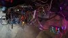
My custom built desk, found it needs to be a bit bigger for projects, oscilloscope, soldering Iron and tester take up to much room. My glass mouse pad is recessed into the top.
 
Top