LED diode expert?

Prawn Connery

Well-Known Member
No. SMDs such as 3030 midpower and 3535 high power LEDs have combined anode/cathode thermal pads for heat dissipation, so the only electrically conductive material you can have in contact with them is the copper trace/track (circuit) itself. That's why when I design a PCB I use large copper pads as the trace with small gaps on the board to separate each trace. All our PCBs are also aluminum, which has better thermal properties thsn FR4.

Most 3535 diodes also have a heat pad which is electrically isolated from the anode and cathode, but it's not fesible (even though technically possible) to have these individual heat pads linked to the aluminum pane as it's too complex and expoensive for very little benefit.

Have a look at these images of our latest High Light 420 "Gen3" LED panel. You can see the copper squares (pads) linking each set of diodes with small gaps in the copper to delineate the trace. A lot of other LED PCB manufacturers do the reverse, with thin copper tracks and large gaps between the tracks, but the more copper the better for us.

This allows us to run our panels at up to 150W each without a heatsink, compared to typical Quantum Boards that can only hanlde about half that power or less without a heatsink. Having the diodes spaced evenly and further apart on the board also helps with heat didssipation.

Gen3panel2.jpg

Gen3Panel1.jpg
 

Prawn Connery

Well-Known Member
Each trace is actually a large square of copper which acts as its own heatsink, as you can see. There is an electrically insulative layer between the copper trace and aluminium PCB base, but the aluminium base does a good job at heasinking on its own. We also 2mm thick PCBs where most other companies use 1.6mm, so this adds thermal mass and rigidity.
 

effexxess

Well-Known Member
Thank you!! This is an amazing insight into how modern LED lights are constructed!

I'm really intrigued by the large copper traces. I disassembled a $50 sale 100w light and took a photo of the aluminum PC board.

Now I can see how almost the entire board is covered with wide copper traces leading from the power to ground.

This Gerylove light looks like it has 13 series in a row.

Is each row is a line of big copper pads, running left to right, that link the anode and cathode on the LED diodes? Thus bridging the current from green positive pad to the red negative pad?
1696788537958.png
 

Attachments

Last edited:

Prawn Connery

Well-Known Member
Thank you!! This is an amazing insight into how modern LED lights are constructed!

I'm really intrigued by the large copper traces. I disassembled a $50 sale 100w light and took a photo of the aluminum PC board.

Now I can see how almost the entire board is covered with wide copper traces leading from the power to ground.

This Gerylove light looks like it has 13 series in a row.

Is each row is a line of big copper pads, running left to right, that link the anode and cathode on the LED diodes? Thus bridging the current from green positive pad to the red negative pad?
View attachment 5333685
That's right. You have 13 series circurts linked in parallel on that board, which is ostensibly a 54V panel. 3030 white phosphor diodes are usually considered to be around 3V each (typically 2.7-2.9V), so 18x 3V = 54V. Each LED will be maximum current rated to around 180-200mA, so that will be 13 x 0.18A = 2.34A x 54V = 126.36W. Again, this figure will likely be lower as we don't normally push the LEDs to their maximum current, so this board would, IMO, be a 100W board (as you pointed out above).

Electron flow in an LED is actually cathode to anode, but conventional DC current flows the opposite to electron flow, which is why you see anode to cathode flow in the above photo.
 

effexxess

Well-Known Member
I have a discussion going with an EE about the PCB design of this light. He says the design is inherently poor because it is using unregulated series of diodes. He claims that, because each series is unregulated, the diodes will be difference light intensity. He introduced the idea of 25% loss of efficiency. He would build the board with each series in parallel?

I don't know what to think. In theory, I guess he could have a point. But now I wonder what is the industry standard and why?
 

Prawn Connery

Well-Known Member
I have a discussion going with an EE about the PCB design of this light. He says the design is inherently poor because it is using unregulated series of diodes. He claims that, because each series is unregulated, the diodes will be difference light intensity. He introduced the idea of 25% loss of efficiency. He would build the board with each series in parallel?

I don't know what to think. In theory, I guess he could have a point. But now I wonder what is the industry standard and why?
Which light?

We voltage match the diodes on our boarrds to within 0.1V so there is no need for ballast resistors, which hurts efficiency.
 

1212ham

Well-Known Member
I have a discussion going with an EE about the PCB design of this light. He says the design is inherently poor because it is using unregulated series of diodes. He claims that, because each series is unregulated, the diodes will be difference light intensity. He introduced the idea of 25% loss of efficiency. He would build the board with each series in parallel?

I don't know what to think. In theory, I guess he could have a point. But now I wonder what is the industry standard and why?
Series strings in parallel is the industry standard. Did the engineer offer a better design?
 
Last edited:

effexxess

Well-Known Member
Which light?

We voltage match the diodes on our boarrds to within 0.1V so there is no need for ballast resistors, which hurts efficiency.
On this light the EE said that the power to the series would be uneven. And that the diode intensity in Series 2 might be different from that on Series 7. And this was because all the series draw off of that one green-tinted positive pad.

Could this be a thing? I don't know much about electronics. Are bar lights wired in series, too?

I find it hard to believe the industry has chosen the wrong approach and am not convinced by my engineer. What would be the advantages to wiring these as parallel circuits?
1700885827934.png
 

Prawn Connery

Well-Known Member
While it's true there will be voltage drop along the trace, the distances are so short that it makes almost no difference. What's more important is to voltage match the LEDs so that those in series have the same voltage drop across each row. That can be the problem with cheap LED PCBs – they don't match the Vf bins and they don't use ballast resistors to even things out.
 

Jonesfamily7715

Well-Known Member
These folks doin like your picture I actually have a stack of boards ready for diodes I'm thinking xpg4
These do 16 3535 in parallel and they are direct thermal path meaning the thermal pad of the diode solders to the actual board no dielectric in the way
 

Attachments

Jonesfamily7715

Well-Known Member
I've actually done a lot of research on thermal management of led lately, I think if someone was to machine these circuit boards out of copper instead of printing them out on an aluminum sheet, we could push these 3030 and 2835 diodes even harder without the consequences of overheating. Another thing, If You spend all that money on the top tech of today it will be obsolete in under a year, led tech is advancing so fast. If we machine high quality boards we would be able to use them over and over. whenever the leds burn out or you just want newer tech on your light just remove the old diodes and replace them with new

I work in a cnc machine shop so I've thought about this alot lol, whenever I get a good design made I will try this.
 

1212ham

Well-Known Member
On this light the EE said that the power to the series would be uneven. And that the diode intensity in Series 2 might be different from that on Series 7. And this was because all the series draw off of that one green-tinted positive pad.

Could this be a thing? I don't know much about electronics. Are bar lights wired in series, too?

I find it hard to believe the industry has chosen the wrong approach and am not convinced by my engineer. What would be the advantages to wiring these as parallel circuits?
View attachment 5346186
Series strings are connected in parallel to avoid wildly high voltage. 234 diodes at 3v each would be 702 volts if connected in series.
 

Prawn Connery

Well-Known Member
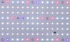
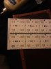
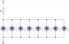
To clarify, here I meant the series replaced by parallel strings, like this:
View attachment 5346362
There is a term called "tolerance stacking" which usually refers to small tolerances adding up to larger tolerances, but in a series circuit it actually has the opposite effect of adding up to smaller tolerances.

Confused?

OK, let's assume that the voltage tolerances for your individual diodes are 0.1V and that your average diode is 3.0V. That means individual diodes could be as high as 3.05V or as low as 2.95V – a spread of 0.1V.

(This is a real-world example, because most Vf bins are 0.1V for 3030 diodes but can be as high as 0.2V for 3535 and other high-powered diodes.)

Now that 0.1V represents a potential difference of 3.4%. And that is the difference you could expect (worst-case scenario) between each of those diodes in parallel. Meaning a 3.4% diffrence in voltage requirements which will draw current away from the higher Vf diodes to the lower Vf diodes – resulting in an imbalance (and potential thermal runaway) between all 8 diodes.

Now let's place those diodes in series. Even though there is a potential difference of 3.4%, we would expect the law of averages to even out the voltages the more diodes we place in series.

So, 8x3.0V = 24V. The maximum voltage would be 8x.3.05V = 24.4V. The minimum would be 8x2.95V = 23.6V A difference of 0.8V or 3.4%.

However, the chances of having maximum and minimum voltages at the end of each series string are highly unlikely – and less likely as you increase the number of diodes in series.

Indeed, you would expect those averages to even out, for the most part, with perhaps only 0.2-0.3V difference between each series string. If there is a 0.3V difference between each string, then that is only a 1% difference in Vf requirements. If we had the same 0.1V difference between each series string (same as the parallel string), then that is a difference of only 0.3% in Vf requirements.

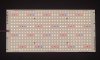
Most 48V LED panels using 3030 diodes (or combinations with 3535 diodfes) have series strings of 16-18 diodes (thereabouts) because 3V (average) x 16 (average) = 48V. And most 24V strips have series strings of 8-9. Each of these strings is then placed in parallel – just like your original LED panel – precisely for the reason I've explained.

The more diodes you have in series, the more even the voltage requirements will be for each string, with less chance of thermal runaway if you place each of those strings in parallel. Also, the higher the voltage for each series string, the lower the impact of voltage drop over longer traces of parallel circuits.

And that is how you design a LED PCB without ballast resistors for each string. However, you do need to get your diode voltage bins as close as you can and the thicker the trace (we use 2oz copper instead of 1oz) again, the less voltage drop (and potential difference) there is between strings.
 

Prawn Connery

Well-Known Member
I've actually done a lot of research on thermal management of led lately, I think if someone was to machine these circuit boards out of copper instead of printing them out on an aluminum sheet, we could push these 3030 and 2835 diodes even harder without the consequences of overheating. Another thing, If You spend all that money on the top tech of today it will be obsolete in under a year, led tech is advancing so fast. If we machine high quality boards we would be able to use them over and over. whenever the leds burn out or you just want newer tech on your light just remove the old diodes and replace them with new

I work in a cnc machine shop so I've thought about this alot lol, whenever I get a good design made I will try this.
There are considerations between copper and aluminium that tilt in favour of aluminum. Namely cost – copper is 3-4x as expensive as aluminium – and strength/rigidity – especially for larger PCBs, such as LED panels.

There is a simple solution to heat management with 3030 diodes, and that is to spread them further apart. This has two benefits: better thermal dissipation, and more even light spread. Even if you double the size of an aluminium PCB, it's still half the cost of copper.

Copper is already used for the trace, so you can increase the thickness of the copper in this area (which is what we do – and we pay for it) as well as the surface area of each copper trace (ditto). If you use a metal base for the PCB, then you need a dielectric material between the copper trace and the base, and that is the main barrier to thermal conductance between the diode/trace and the main PCB structure.

Reusing PCBs is not as simple as it sounds, because you often damage the solder mask when you de-solder and resolder, so you may need to strip and reapply the solder mask between reuse. Especially for LED PCBs, we use a reflective solder mask that is specifically design for use on LED PCBs. It is made by Taiyo.
 

Jonesfamily7715

Well-Known Member
There are considerations between copper and aluminium that tilt in favour of aluminum. Namely cost – copper is 3-4x as expensive as aluminium – and strength/rigidity – especially for larger PCBs, such as LED panels.

There is a simple solution to heat management with 3030 diodes, and that is to spread them further apart. This has two benefits: better thermal dissipation, and more even light spread. Even if you double the size of an aluminium PCB, it's still half the cost of copper.

Copper is already used for the trace, so you can increase the thickness of the copper in this area (which is what we do – and we pay for it) as well as the surface area of each copper trace (ditto). If you use a metal base for the PCB, then you need a dielectric material between the copper trace and the base, and that is the main barrier to thermal conductance between the diode/trace and the main PCB structure.

Reusing PCBs is not as simple as it sounds, because you often damage the solder mask when you de-solder and resolder, so you may need to strip and reapply the solder mask between reuse. Especially for LED PCBs, we use a reflective solder mask that is specifically design for use on LED PCBs. It is made by Taiyo.
The cost of copper Is a mofucker, but that all depends on your own personal source, There is a metal scrapping place close to where I live and lines of homeless people in line 5 days a week with shopping carts full of aluminum and copper, I've been thinking how easy it would be to talk them out of their copper maybe even pay em in flower, or alcohol lol. For my personal prototyping I can just grab some out of the scrap bins at work but on a commercial level where you have to turn a profit, aluminum becomes a lot more appealing.
 

Prawn Connery

Well-Known Member
That's cool if you can turn scrap copper into a PCB. We tried a few different PCB manufacturers in China a few years ago and the quality was variable. Most companies couldn't get it right and their PCBs were not perfectly flat, but curled at the edges. The only company that could do it properly used a double-sided guillotine.
 
Top