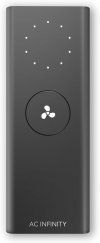
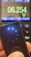
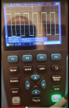
Hey, thanks for replying!
So, I have a "good" osciloscope, but still in the learning curve of it and all ESP / Electronics stuff.
Yeah, so am I. And I spent time learning ESPHome, then openHASP, and Tasmota. Plus I learned a lot of electronics while working this out. I know more than some, but not as much as many people who have posted here before.
As long as the fan is PWM, then the main purpose of the o-scope is to find out what the operating frequency is. Then, when you've got ESPHome working on the ESP32, my feeling is you're better off double-checking the PWM output to be sure it matches the fan PWM signal before plugging your board into the fan. In my case, I lost a fan (about $85, if I remember) due to carelessness with contacts. But if you have a good scope, there's no reason to risk that somehow the ESP32's PWM does NOT match the fan.
Side note on this: I did test the other systems, openHASP, and Tasmota. I found that ESPHome lets you set the PWM frequency and the others have a set 40Khz frequency. The AC Infinity fans (at least he one most people use here, works with 10Khz. If I recall properly, and that's a big IF, I think the fan's normal frequency is 14Khz. (Why an oddball one? I don't know - but I can't figure out a lot about this company.) I found out the limits of my cheap o-scope when I tried to read a 40Khz frequency. I don't remember if that test was on Tasmota or openHASP. (I think it was Tasmota, but not sure.) I recompiled it for a 10Khz PWM signal, but it still didn't show up properly on my cheap o-scope! It'll be a while before I can get back to the dirt level work on this, but I will need to buy a decent o-scope, so I can read a 40Khz signal. (That'll also be a big help on other projects.)
I'll dig out how can I measure that frequency.
Basically, you'll need to connect to the ground and to the signal line to read it. Since these fans use a USB-C connection, look for a breakout diagram of the USB-C connectors. I can never remember things like model numbers (except for my beloved classic convertible that always needs more work!) The USB-C connector is quite different from earlier versions, with more than just 4 pins (GND, +5V, and signals). Also, the fans use +10VDC instead of +5VDC. If I recall, the fans use GND, +10VDC (again, on the +5VDC line for USB standards), and I'm pretty sure the PWM signal is on the D+ line, but check that out. Again - I can forget things like that and I'm not looking over notes right now.
You can make your own USB-C breakout box using something
like this (from Amazon). And I'm pretty sure
this is the USB-C connector I'm using now. The pins are spaced so they work on a breadboard and, of course, you can easily use them on most PCB designs later.
I was asking because I could easily measure the different voltages with the original controller (signal wire + / GND -), but I understand this is a different circuit.
I'm not sure what you mean by "a different circuit." If you use a USB-C breakout box, or panel like I linked to, then you have the fan and speed controller connected by a USB-C cable. (Well, technically, 2 cables and a breakout panel, but, still, you have the controller talking to the fans through the USB-C cable.) that makes it kind of a "black box" situation. As long as you know exactly what signals are going on what wirees on the USB-C cable, you can duplicate them. The fan doesn't care about what kind of circuit is in the controller, or anything about the controller. All it cares about is that the signals are the same as the ones that'd come from the controller.
About the code, I went to search and now I understand there's no code per se. I really wanted to code it like standalone and then integrate with HA (got coding skills, learning C++). It's a different scenario tho, and not related to this thread I guess.
Ah - yes. I get what you're saying. Nope. No code for ESPHome, just a config file. HA has an ESPHome add-on you can use, so you can write your config file in it and save it. If I remember, compiling and uploading is a one-button function. (Well maybe 2, but I think it's one.) I changed to using a command line tool and my own editor (which makes it possible for me to use git, which I'm new to, so I can track my versions). I use esptool.py for compiling. I can't remember right off, but I think I use one command to compile and another to upload. It takes a bit more effort, but it works better. For one thing, I run HA on a Pi, which a lot of people do, and that compiles slower than my desktop. Plus, as I said, I have versioning control, and, overall, it gives me more control.
Honestly, while I like an excuse to program in C or C++ (and haven't had a good one in years - sadly) - and even more, love if I have a reason to code in Assembler (which I've hardly ever had to do since I sold my Apple //e in the late '80s). But it's a lot easier to handle this in something like ESPHome, or Tasmota, or openHASP. They do a lot of the heavy lifting for you. They're not perfect and all three are evolving, but they can make many tasks easier than writing the code - and they handle communication with other ESP32 systems through MQTT easier, as well as working with HA. (I use the ESPHome plugin, but you can use MQTT - which I suspect I'll switch to even for ESPHome <-> HA communication.)
I don't mind discussing the ESP systems like ESPHome and the others here, as relates to the fan controller. I think that's quite within the topic. If you want to discuss more about that, feel free to PM me.
Personal note: I may have been a bit abrupt in my earlier replies. It seemed like you were asking for a simplified version of everything, kind of a, "Okay, so break this down so I can go out and buy the parts and string 'em together." It's hard to tell, sometimes, just what a person's motivation is. I have frequently run into people who basically say, "Do this for me." (Happened all the time when I was teaching!) I basically said what I did because I knew if you were interested in learning, you'd be back asking questions like this. I'm always glad to help people who want to learn and will put in the effort to figure it all out. (I have to add that sometimes life and work and projects can delay my responses!)
Anyway, thanks a lot for your answer! Just one last thing... Did you wire the mosfet like the OP? using vOUT+ for +10v and vOUT- for PWM output to fan?
I changed to something else. If I recall, they use a MOSFET on a PCB. I think it included 2 MOSFETs and maybe some resistors onboard as well. Possibly even capacitors, but I don't remember for sure just what is on it. Instead I used
this MOSFET because it's easier to plug into a breadboard and easier to mount on a PCB. I think it's a little cheaper, but I don't remember how much or if that was a big reason I used it.
Wiring is critical on this, since PNP and NPN transistors need to be wired differently. Here's a snapshot of part of an earlier schematic of mine (honestly, the one I could pull up a screen shot of the fastest!). R1 goes to the +10V line from the fan. I know it branches off - honestly, the 2nd line from above R1 doesn't matter for this discussion.
The other line coming in below R1 and above Q1 is the signal line to the fan. Pin 3, the collector, goes to ground. (On my system, the ESP32 ground is connected to the ground line from the fan.) This is an NPN transistor, so the load goes on the "high" (referring to the voltage direction) end of it. In this case, the load is that line below R1 and above Q1, which connects to the fan's motor control circuit.
I haven't mentioned the base, or pin 2. That connects to your ESP32 PWM output. When it's off, current won't flow from the +10VDC line through to the ground, which also means it won't provide a signal to the fan, when there is no current to the base.

I hope this helps!


