born2killspam
Well-Known Member
I've created/adapted this for those who need a timer that can be programmed to cycle at periods other than 24 hrs.. Good for things like fans/pumps/heaters/lights..
This version has no second resolution.. Its extremely easy to whip up a short period timer as opposed to something that can handle hours/days, but this circuit could be adapted for a high precision short period timer (By adjusting the counter(s) in ICs 1/2) that isn't susceptable to heat fluctuations like 555/RC timers since it uses a crystal oscillator..
Most specialty timers are very expensive for no good reason.. Parts for this should run $10-20 I imagine.. Eventually I'll build a parts list, but its pretty obvious expept for exact numbers of trivial components..
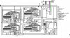
Circuit Operation:
Its actually a really simple circuit for its size.. Each area of the schematic does a stage..
ICs 1&2 and the components near them create the one minute clock, IC's 4&5 count these minutes and each trigger the relay once per day cycle.. (IC4 turns on the relay, IC5 turns it off).. ICs 6&7 just control when the relay gets triggered by counting up to their set delays, then resetting the counters in ICs 4&5 respectively (on the first cycle only).. Basically when the relay is supposed to come one, IC4 gets reset to 0.. It then counts as many minutes as are in a day cycle and then turns it on again.. Same thing with the off switch, IC7 waits until the relay is supposed to go off, then resets IC5 so that its sync'd to keep turning off at the same time each day.. In the original circuit, ICs 6&7 did not exist.. It was set up with normally closed push switches that manually got pressed the first day at the proper on/off times, then IC's 4&5 just repeated that process every day cycle.. (Again a day cycle is as many minutes as ICs 4&5 are set to count before resetting)..
The 9V battery is just there so the counters don't lose their counts if the power goes out..
7 segment display(s) for time readout could easily be added, but I don't want to clutter up the schematic before ppl get a chance to discuss the guts of the logic..
Its critical that the load is solidly connected to the relay with suitably guaged wire!
I haven't built/tested this, but its based off a proven circuit.. Still though it would be better to proof/discuss it before declaring it finalized..
This version has no second resolution.. Its extremely easy to whip up a short period timer as opposed to something that can handle hours/days, but this circuit could be adapted for a high precision short period timer (By adjusting the counter(s) in ICs 1/2) that isn't susceptable to heat fluctuations like 555/RC timers since it uses a crystal oscillator..
Most specialty timers are very expensive for no good reason.. Parts for this should run $10-20 I imagine.. Eventually I'll build a parts list, but its pretty obvious expept for exact numbers of trivial components..
Circuit Operation:
Its actually a really simple circuit for its size.. Each area of the schematic does a stage..
ICs 1&2 and the components near them create the one minute clock, IC's 4&5 count these minutes and each trigger the relay once per day cycle.. (IC4 turns on the relay, IC5 turns it off).. ICs 6&7 just control when the relay gets triggered by counting up to their set delays, then resetting the counters in ICs 4&5 respectively (on the first cycle only).. Basically when the relay is supposed to come one, IC4 gets reset to 0.. It then counts as many minutes as are in a day cycle and then turns it on again.. Same thing with the off switch, IC7 waits until the relay is supposed to go off, then resets IC5 so that its sync'd to keep turning off at the same time each day.. In the original circuit, ICs 6&7 did not exist.. It was set up with normally closed push switches that manually got pressed the first day at the proper on/off times, then IC's 4&5 just repeated that process every day cycle.. (Again a day cycle is as many minutes as ICs 4&5 are set to count before resetting)..
The 9V battery is just there so the counters don't lose their counts if the power goes out..
7 segment display(s) for time readout could easily be added, but I don't want to clutter up the schematic before ppl get a chance to discuss the guts of the logic..
Its critical that the load is solidly connected to the relay with suitably guaged wire!
I haven't built/tested this, but its based off a proven circuit.. Still though it would be better to proof/discuss it before declaring it finalized..