RoBoMikE510
Member
Assuming you have an ATX PSU (most common today)
Figure i post some useful info from google to help those who are going micro/stealth grow. I noticed people using cellphone adapters cut and twist and electric tape were used to power the accessories that are essential to a successful harvest. Using the PSU ( power supply unit) won't sacrifice the purpose of having a sleek, stealthy grow unit. Don't have tons of wires hanging out the box sealed by massive amounts of duck tape resembling a tangled birds nest. with mounds of wires filling an electrical multi adapter!! why ? why?
Heres how: """"" Safety is key leave unplugged for an hour or to b4 you dissect the bad boy"
Steps
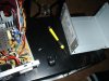
Unplug the power cord from the back of the computer. "Harvest" a power supply from a computer by opening up the case of the computer, locating the gray box that is the power supply unit, tracing the wires from the power supply to the boards and devices and disconnecting all the cables by unplugging them.
Remove the screws (typically 4) that attach the power supply to the computer case and remove the power supply.
Cut off the connectors (leave a few inches of wire on the connectors so that you can use them later on for other projects).
Discharge the power supply by either letting it sit unconnected for a few days. Some people suggest attaching a 10 ohm resistor between a black and red wire (from the power cables on the output side), however this is only guaranteed to drain the low voltage capacitors on the output - which aren't dangerous to begin with! It could leave the high-voltage capacitors charged, resulting in a potentially dangerous - or even lethal - situation.
Gather the parts you need: binding posts (terminals), a LED with a current-limiting resistor, a switch (optional), a power resistor (10 ohm, 10W or greater wattage, see Tips), and heat shrink tubing.
Open up the power supply unit by removing the screws connecting the top and the bottom of the PSU case.
Bundle wires of the same colors together. If you have wires not listed here (brown, etc), see the Tips.
The color code for the wires is: Red = +5V, Black = Ground (0V), White = -5V, Yellow = +12V, Blue = -12V, Orange = +3.3V, Purple = +5V Standby (not used), Gray = power is on (output), and Green = Turn DC on (input).
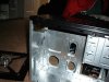
Drill holes in a free area of the power supply case by marking the center of the holes with a nail and a tap from the hammer. Use a Dremel to drill the starting holes followed by a hand reamer to enlarge the holes until they are the right size by test fitting the binding posts. Also, drill holes for the power ON LED and a Power switch (optional).
Screw the binding posts into their corresponding holes and attach the nut on the back.
Connect all the pieces together.
Connect one of the red wires to the power resistor, all the remaining red wires to the red binding posts;
Connect one of the black wires to the other end of the power resistor, one black wire to a resistor (330 ohm) attached to the cathode (shorter lead) of the LED, one black wire to the DC-On switch, all the remaining black wires to the black binding post;
Connect the white to the -5V binding post, yellow to the +12V binding post, the blue to the -12V binding post, the gray to the anode (longer lead) of the LED;
Note that some power supplies may have either a gray or brown wire to represent "power good"/"power ok". (Most pSU's have a smaller orange wire that is used for sensing-- 3.3V- and this wire is usually paired at the connector to another orange wire. Make sure this wire is connected to the other orange wires, otherwise your lab power supply won't stay on.) This wire should be connected to either an orange wire (+3.3V) or a red wire (+5V) for the power supply to function. When in doubt, try the lower voltage first (+3.3V). If a power supply is non ATX or AT compliant, it may have its own color scheme. If yours looks different that the pictures shown here, make sure you reference the position of the wires attached to the AT/ATX connector rather than the colors.
Connect the green wire to the other terminal on the switch.
Make sure that the soldered ends are insulated in heatshrink tubing.
Organize the wires with a electrical tape or zip-ties.
Check for loose connections by gently tugging on them. Inspect for bare wire, and cover it to prevent a short circuit. Put a drop of super-glue to stick the LED to its hole. Put the cover back on.
Plug the power cord into the back and into an AC socket. Flip the main switch on the PSU. Check to see if the LED light comes on. If it has not, then power up by flipping the switch you placed on the front. Plug in a 12V bulb into the different sockets to see if the PSU works, also check with a digital voltmeter. It should look good and work like a charm!
I should have made a video my eyes hurt too..!!!
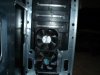
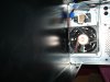
My grow box accessories powered by ATX PSU 700 watts
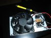
2 FANS power=.05a each
Color code= RED
2 L.E.D. power= No clue
color code= 12v yellow
2 CFL's power= 120v each 20 w 2700k
Hopefully an lcd gaming thermal take temp gauge as well..
hope it helped out..
PC Grower
RoBoMike
Figure i post some useful info from google to help those who are going micro/stealth grow. I noticed people using cellphone adapters cut and twist and electric tape were used to power the accessories that are essential to a successful harvest. Using the PSU ( power supply unit) won't sacrifice the purpose of having a sleek, stealthy grow unit. Don't have tons of wires hanging out the box sealed by massive amounts of duck tape resembling a tangled birds nest. with mounds of wires filling an electrical multi adapter!! why ? why?
Heres how: """"" Safety is key leave unplugged for an hour or to b4 you dissect the bad boy"
Steps
Unplug the power cord from the back of the computer. "Harvest" a power supply from a computer by opening up the case of the computer, locating the gray box that is the power supply unit, tracing the wires from the power supply to the boards and devices and disconnecting all the cables by unplugging them.
Remove the screws (typically 4) that attach the power supply to the computer case and remove the power supply.
Cut off the connectors (leave a few inches of wire on the connectors so that you can use them later on for other projects).
Discharge the power supply by either letting it sit unconnected for a few days. Some people suggest attaching a 10 ohm resistor between a black and red wire (from the power cables on the output side), however this is only guaranteed to drain the low voltage capacitors on the output - which aren't dangerous to begin with! It could leave the high-voltage capacitors charged, resulting in a potentially dangerous - or even lethal - situation.
Gather the parts you need: binding posts (terminals), a LED with a current-limiting resistor, a switch (optional), a power resistor (10 ohm, 10W or greater wattage, see Tips), and heat shrink tubing.
Open up the power supply unit by removing the screws connecting the top and the bottom of the PSU case.
Bundle wires of the same colors together. If you have wires not listed here (brown, etc), see the Tips.
The color code for the wires is: Red = +5V, Black = Ground (0V), White = -5V, Yellow = +12V, Blue = -12V, Orange = +3.3V, Purple = +5V Standby (not used), Gray = power is on (output), and Green = Turn DC on (input).
Drill holes in a free area of the power supply case by marking the center of the holes with a nail and a tap from the hammer. Use a Dremel to drill the starting holes followed by a hand reamer to enlarge the holes until they are the right size by test fitting the binding posts. Also, drill holes for the power ON LED and a Power switch (optional).
Screw the binding posts into their corresponding holes and attach the nut on the back.
Connect all the pieces together.
Connect one of the red wires to the power resistor, all the remaining red wires to the red binding posts;
Connect one of the black wires to the other end of the power resistor, one black wire to a resistor (330 ohm) attached to the cathode (shorter lead) of the LED, one black wire to the DC-On switch, all the remaining black wires to the black binding post;
Connect the white to the -5V binding post, yellow to the +12V binding post, the blue to the -12V binding post, the gray to the anode (longer lead) of the LED;
Note that some power supplies may have either a gray or brown wire to represent "power good"/"power ok". (Most pSU's have a smaller orange wire that is used for sensing-- 3.3V- and this wire is usually paired at the connector to another orange wire. Make sure this wire is connected to the other orange wires, otherwise your lab power supply won't stay on.) This wire should be connected to either an orange wire (+3.3V) or a red wire (+5V) for the power supply to function. When in doubt, try the lower voltage first (+3.3V). If a power supply is non ATX or AT compliant, it may have its own color scheme. If yours looks different that the pictures shown here, make sure you reference the position of the wires attached to the AT/ATX connector rather than the colors.
Connect the green wire to the other terminal on the switch.
Make sure that the soldered ends are insulated in heatshrink tubing.
Organize the wires with a electrical tape or zip-ties.
Check for loose connections by gently tugging on them. Inspect for bare wire, and cover it to prevent a short circuit. Put a drop of super-glue to stick the LED to its hole. Put the cover back on.
Plug the power cord into the back and into an AC socket. Flip the main switch on the PSU. Check to see if the LED light comes on. If it has not, then power up by flipping the switch you placed on the front. Plug in a 12V bulb into the different sockets to see if the PSU works, also check with a digital voltmeter. It should look good and work like a charm!
I should have made a video my eyes hurt too..!!!
My grow box accessories powered by ATX PSU 700 watts
2 FANS power=.05a each
Color code= RED
2 L.E.D. power= No clue
color code= 12v yellow
2 CFL's power= 120v each 20 w 2700k
Hopefully an lcd gaming thermal take temp gauge as well..
hope it helped out..
PC Grower
RoBoMike