Experienced Electrician! Here to Answer Any and All Growroom Electrical Questions

ruffrider

Active Member
Hello and Thank you for the thread!
I am trying to build a hanging light and I got to a snag....
For a base I am using a 6' 12 socket wall mount usually used to supply off a wall.

I figured three wires, no problem, wish you could hear the sarcasm.
Get it home and creat my cord, I removed the female end and stripped back to expose my wires.

I look into the back of this simple strip and find its set up, wired to run to a second base.
Three wires on each end!

Can I just cap off the ones I don't need???
please help, it will be a 24 bulb hanging bar when complete.
thanks !!
I assume the wires will you be out in the open right and not behind drywall?
If so then yeah you sure can just go ahead cap them and put some electrical tape over the caps/wire for reassurance.

Or if the hanging socket is attached to a junction box cap the wires and tape like stated then put them inside the junction box and cover it with the cap.
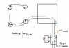
 

ruffrider

Active Member
Not sure how complex my question is but here goes:

The back half of my grow space lost all power to the back wall, its not affecting any other part of the space, just the back wall, 2 wall sockets and a outdoor security light are down. Checked the breakers and all is good.

Some details:

House built in '53, everything still original
Power loss was noticed after bathroom remodel

Hopefully the experts can keep me from getting fried :P

CK
Its normal in old house for different things to use the same circuit.
Flip off all the breakers in your panel. Sometimes a tripped breaker wont look like it even tho it is.

Also since there was a bathroom remodel it could have been improperly rewired causing it to instantly short and trip the the breaker, also could just be loose wiring that needs to be repaired.
 

spek9

Well-Known Member
Not sure how complex my question is but here goes:

The back half of my grow space lost all power to the back wall, its not affecting any other part of the space, just the back wall, 2 wall sockets and a outdoor security light are down. Checked the breakers and all is good.

Some details:

House built in '53, everything still original
Power loss was noticed after bathroom remodel

Hopefully the experts can keep me from getting fried :P

CK
Check the GFCI in the bathroom. If this is a new reno and was done properly, the outlet in the bathroom would have been replaced with a ground fault. Perhaps they tied into that somehow. Check to see that the Test button isn't engaged (to do so, press the 'Reset' button.

-spek
 

captiankush

Well-Known Member
Its normal in old house for different things to use the same circuit.
Flip off all the breakers in your panel. Sometimes a tripped breaker wont look like it even tho it is.

Also since there was a bathroom remodel it could have been improperly rewired causing it to instantly short and trip the the breaker, also could just be loose wiring that needs to be repaired.
Check the GFCI in the bathroom. If this is a new reno and was done properly, the outlet in the bathroom would have been replaced with a ground fault. Perhaps they tied into that somehow. Check to see that the Test button isn't engaged (to do so, press the 'Reset' button.

-spek
spek & ruff, I appreciate the replies

problem was was due to an incomplete circuit. I shutdown breakers and checked the outlet nearest that part of the house ( u guessed it, in the bathroom) and found the ground disconnected. Reconnected the ground, turn on the breakers and I am good to go.

CK
 

ruffrider

Active Member
spek & ruff, I appreciate the replies

problem was was due to an incomplete circuit. I shutdown breakers and checked the outlet nearest that part of the house ( u guessed it, in the bathroom) and found the ground disconnected. Reconnected the ground, turn on the breakers and I am good to go.

CK
I figured i'd be something like that, you'd be surprised how many calls we get about shady wiring. Shit some people just snip their wires and leave them live behind the wall no caps or nothing.

Glad to hear your back up and running tho buddy, best of luck to you and your grow ! :weed:
 
View attachment 2885491Hi Bricktown73
How would I wire up 5sockets ouvt of a bathroom light unit so that they connect with 4 larger CFL mounts as per the pictures attached. They seem to be wired in parallel. Should I earth the lot to the metal box casing? I had the 4 x 48 wayters runnimg nice but want to add 5 x 23 watts for a total of 307 watts withoit burning myIMG_20131107_173752.jpgView attachment 2885490IMG_20131107_173752.jpg house down.
 

hibok

Well-Known Member
View attachment 2885491Hi Bricktown73
How would I wire up 5sockets ouvt of a bathroom light unit so that they connect with 4 larger CFL mounts as per the pictures attached. They seem to be wired in parallel. Should I earth the lot to the metal box casing? I had the 4 x 48 wayters runnimg nice but want to add 5 x 23 watts for a total of 307 watts withoit burning myView attachment 2885489View attachment 2885490View attachment 2885489 house down.
the power source cable probably 14/2 AWG cooper, you just need to bond the metal house to the copper bare wire, which should be bonded to device box ( box where the switch is) that from that device box to the panel. than you connect the white / neutral, to the sliver screw / side shell of the light, the black/live/hot will than be connect to the bronze screw/ middle of the shell. that you just connect the other lights in series. remember to have the power off from the main panel before doing any work with electricity or get a professional.

other notes : 1.6 amps for the original four and by going up another 5 lights for a total of 307 watts you will be using 2.6 amps. I dont think you will be popping any breakers, i would think it the ciruit would be running on a 15 amp breaker. which gives you 9.4 amps for other devices to playing around with if you stay in code of 80% load of the 15 amp breaker.

questions are you adding those five in separate metal boxes or in the same housing?
if serparate you will have to bond each metal box from that big box. see picture
 

Attachments

powerslide

Well-Known Member
I have what has always been my veg and flower room just always went back and forth between the two. I am going to try to get two runs in this winter a little bit perpetual and want to add a seperate room. Now i dont have enough power/amps whatever on the 110 side. I have a 240 plug for my welder in my shop and want to build a small panel to plug into it to run the "veg" room and leave the 110 to the flower room. My flower room is a cellar and i dont want to deal w/ pulling 240 into it because its already setup. Anyone point me to something that shows me how to build a panel? I have lots of car knowledge and DYI skill but electric scares me.
 

powerslide

Well-Known Member
No electricians here?

I have what has always been my veg and flower room just always went back and forth between the two. I am going to try to get two runs in this winter a little bit perpetual and want to add a seperate room. Now i dont have enough power/amps whatever on the 110 side. I have a 240 plug for my welder in my shop and want to build a small panel to plug into it to run the "veg" room and leave the 110 to the flower room. My flower room is a cellar and i dont want to deal w/ pulling 240 into it because its already setup. Anyone point me to something that shows me how to build a panel? I have lots of car knowledge and DYI skill but electric scares me.
 

Abiqua

Well-Known Member
I have a small voltage DC question about fans and potentiometers.

I am running a microcab, sorry big boys, need to learn before I step up!

Is there a way to run two fans in parallel off one power supply and separating the circuit so that only one fan is controlled with a 1k ohm pot, while the other fan just uses the 12v signal unencumbered? Or will each fan need a pot? Or....plan b with LM317's?

Right now I am rewiring it, but the current config has the power supply, 12v exhaust fan and 12v interior fan wired after the pot all running into a terminal strip to connect in parallel, but both fans are being voltage controlled and terribly [5k ohm pot][way too high of restistance, I know, I asked for advice and then realized the mistake.]

Specs:
12V 500mA power supply
12v Fans .215 mA apiece
5k ohm pot [I have 1k ohm pots] [These are way overkill I realize for these specs, but the only affordable pots I could find with 500mA ratings.

Thank you...hopefully that is not too illegible
 

Stevie51

Active Member
Is there a way to run two fans in parallel off one power supply and separating the circuit so that only one fan is controlled with a 1k ohm pot, while the other fan just uses the 12v signal unencumbered?


Yes you can do it that way. Assuming that your potentiometer has three terminals, connect one outer terminal to the 12 volts power, and connect the other outer terminal to the fan wire. Connect the center terminal to one of the outer terminal using a jumper wire. If you feel that the 1k ohm pot has too much resistance, you can simply change that resistance value by adding a resistor (rated for 3 watts) in parallel across the outer terminals of the pot to give you a lower maximum resistance.
 

Abiqua

Well-Known Member
Is there a way to run two fans in parallel off one power supply and separating the circuit so that only one fan is controlled with a 1k ohm pot, while the other fan just uses the 12v signal unencumbered?

Yes you can do it that way. Assuming that your potentiometer has three terminals, connect one outer terminal to the 12 volts power, and connect the other outer terminal to the fan wire. Connect the center terminal to one of the outer terminal using a jumper wire. If you feel that the 1k ohm pot has too much resistance, you can simply change that resistance value by adding a resistor (rated for 3 watts) in parallel across the outer terminals of the pot to give you a lower maximum resistance.

Stevie here is my diagram with the 5k pot. I can't isolate the interior fan, both fans are still acting as one, wired in paralell, here is my diagram.

Thanks!fan schematic [my own].JPG
 

SnapsProvolone

Well-Known Member
My washer is on a 20a circuit. If I were to run an extension cord to an Apollo 14 surge protector which is rated for 15a and 1800w, would this be safe as long as I stay under 80% of 1800w which is 1440w?

I would not run the washer when the extension cord is plugged in
Might work. Not safe. Deviced with 14 gauge wire won't be adequately protected by the 20 amp overcurrent protection.
 

Stevie51

Active Member
Stevie here is my diagram with the 5k pot. I can't isolate the interior fan, both fans are still acting as one, wired in paralell, here is my diagram.

Thanks!View attachment 2899482
Red wire from 12 volts power supply to terminal #1 on the pot. Red wire from fan to terminal #3 on the pot. Jumper wire from terminal #2 to terminal #3 on the pot. Black wire from the fan to the black wire from the 12 volts power supply. There should be no black wire going to the pot. Why are you using the 5k pot? You should be using the 1k pot.
 

spek9

Well-Known Member
Red wire from 12 volts power supply to terminal #1 on the pot. Red wire from fan to terminal #3 on the pot. Jumper wire from terminal #2 to terminal #3 on the pot. Black wire from the fan to the black wire from the 12 volts power supply. There should be no black wire going to the pot.
Although I'm a relative newb here, I throw my current RIU weight behind Stevie. I, as an experienced resi electrician who has reasonable understanding of large-scale (3-phase) wiring, would personally take his advice.

-spek
 

hibok

Well-Known Member
No electricians here?
details on your veg room or the new room you want 240volts
ie. wattage of each bulb. how many bulbs, are you going to need other outlets for say fans, exhaust fans, heaters, AC, pumps. etc....
from there we can determine your demand load and see what we can hook up.
 

Manystacks

New Member
Hey guys, migrated here from another site. A site that blames broad mites on everything. lol

I have always been fortunate to have sparkys very close to me. I have relocated and now I am dealing with the "f....I shouldve watched him.." mode.

I have a Titan Helios 8 light controller. Now in the past I have always used HPH-8s from Sent, and there has always been just three wire to connect ( green black white). In this particular location, the Titan is what I was dealt.

When I open the titan box, I am presented with 4 ...the green, obviously ground. But, then there is 3 more places to place wiring. I am confused and wanting to know why there is 4, including the ground hook up? Of those three open spots after i connect my ground, does it matter where my Black, and White wires go?

Here is the PDF manual to the titan helios 8, i understand if you dont want to click something from someone new.
http://www.titancontrols.net/media/8221/702677_helios8_instructions.pdf At the bottom you see the wiring diagram. They dont show the ground, the ground I understand. Just want to understand why there is those three? I always have just used Ground-green and a black and white. That diagram shows 3, not including ground. Sorry just trying to be specific and im becoming long winded lol
 
Top