Unclebilly
Member
Hey guys, so I’ve learnt everything I know from RIU so looking to give something back. maybe I can’t give any grow advice just yet but I’m a better fabricator than gardener I guess.
I’m in the process of building my own led fixture for flowering my 2.5’x4’ area.
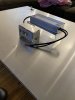
I designed it using a mean well HLG 320H 42B driver and 11 eb gen 2 strips (1120mm 3500k) 39v @ 700ma
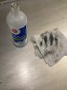
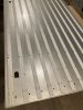
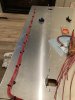
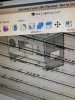
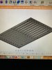
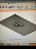
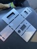
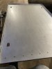
I designed the canopy and mini control box on fusion 360 and sent it out for CNC laser cutting. I designed it in a way that I can fold the edges by hand as I don’t have a press brake. It was laser cut from 0.090” 5056 aluminum. I downloaded the 3D model of the eb strips I’m using so I can space it all out perfectly in the model and I transcribed the hole location into my laser cutting file so I don’t have to measure by hand when mounting. I will be using 2 way thermal transfer tape (Amazon) and aluminum pop rivets to secure the strips.
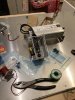
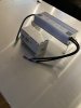
I have the control box laid out as such:
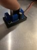
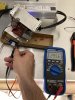
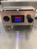
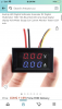
On off toggle switch, then a small digital voltage and current readout. Which I will display the data for 1 of the 11 legs of the parallel strip wiring. So I can see what voltage and amperage I’m running while dimming. (Not necessary but I thought it was cool and for 10 bucks on Amazon, why not). Then, I have a 100k potentiometer wired with a 10k ohm resistor in series for dimming.
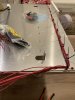
everything was modeled and holes marked in the 3d model so I just fold up the pieces and pop rivet it together I made sure that none of my rivets for the control box or driver mount will interfere with the eb strips. I also drew in these little flip up tabs to hang The light.
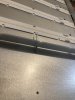
I drew a 3/4” lip all around the canopy to be bent down 90 degrees for a couple of reasons
1. So I can set the light down on the floor without sitting it on the diodes themselves
2. It gives the large flat canopy a TON more strength compared to if it remained one flat piece of aluminum.
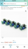
I also drew in holes evenly spaced for the wire to poke through the canopy to wire the strips to the control box. Where I will be using a 12 terminal block to breakout from the driver to each strip both on positive and negative wires. I am 3D printing custom sized grommets to prevent any wire chafing on the aluminum edges.
I am really excited to get this thing together so I wanted to share my journey along the way.
my plants are 9 weeks into veg on a cheapie 150w QB so i really want to flip them onto 12/12 with this light ASAP but trying not to cut any corners!
I’m in the process of building my own led fixture for flowering my 2.5’x4’ area.
I designed it using a mean well HLG 320H 42B driver and 11 eb gen 2 strips (1120mm 3500k) 39v @ 700ma
I designed the canopy and mini control box on fusion 360 and sent it out for CNC laser cutting. I designed it in a way that I can fold the edges by hand as I don’t have a press brake. It was laser cut from 0.090” 5056 aluminum. I downloaded the 3D model of the eb strips I’m using so I can space it all out perfectly in the model and I transcribed the hole location into my laser cutting file so I don’t have to measure by hand when mounting. I will be using 2 way thermal transfer tape (Amazon) and aluminum pop rivets to secure the strips.
I have the control box laid out as such:
On off toggle switch, then a small digital voltage and current readout. Which I will display the data for 1 of the 11 legs of the parallel strip wiring. So I can see what voltage and amperage I’m running while dimming. (Not necessary but I thought it was cool and for 10 bucks on Amazon, why not). Then, I have a 100k potentiometer wired with a 10k ohm resistor in series for dimming.
everything was modeled and holes marked in the 3d model so I just fold up the pieces and pop rivet it together I made sure that none of my rivets for the control box or driver mount will interfere with the eb strips. I also drew in these little flip up tabs to hang The light.
I drew a 3/4” lip all around the canopy to be bent down 90 degrees for a couple of reasons
1. So I can set the light down on the floor without sitting it on the diodes themselves
2. It gives the large flat canopy a TON more strength compared to if it remained one flat piece of aluminum.
I also drew in holes evenly spaced for the wire to poke through the canopy to wire the strips to the control box. Where I will be using a 12 terminal block to breakout from the driver to each strip both on positive and negative wires. I am 3D printing custom sized grommets to prevent any wire chafing on the aluminum edges.
I am really excited to get this thing together so I wanted to share my journey along the way.
my plants are 9 weeks into veg on a cheapie 150w QB so i really want to flip them onto 12/12 with this light ASAP but trying not to cut any corners!
Attachments
-
 B393B033-5B51-446E-B715-7EDD60D2608A.jpeg5.5 MB · Views: 54
 -
 B9889F9D-2AF0-4FB8-92D5-A71DF356C9C6.jpeg3.9 MB · Views: 51
 -
 29C39BB9-BA2D-44D5-A743-136D7C7EA3C4.jpeg4.2 MB · Views: 51
 -
 E1030CD6-38F9-4874-885E-2897FA6EC08C.jpeg1.7 MB · Views: 51
 -
 908EBD4D-76F9-4982-9330-C58E5B5CB0B6.jpeg2 MB · Views: 49
 -
 FFFF6212-7D67-4F64-A8EF-0AD36B085B3E.jpeg1.7 MB · Views: 48
 -
 EC8E10CA-9F1B-49FB-9637-8C83283270A7.jpeg1.7 MB · Views: 42
 -
 6B056547-1E13-4AB1-A7EE-CA6A30DEB941.jpeg1.4 MB · Views: 43
 -
 7F4CBE6B-0D62-48FF-A7D9-B0526F492547.jpeg1.5 MB · Views: 44
 -
 EF097E4F-EEF8-44E6-BBFA-1C342E163BFB.jpeg1.3 MB · Views: 42