Economical multi LED Chip Projects for Growing

DIY-HP-LED

Well-Known Member
A Test Corner Lamp Design for a friend
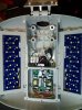
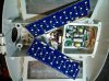
This is a prototype corner lamp I'm creating for a friend, I'm testing the cooling ability of the design. This light was originally going to be a 5 chip design, but the bottom LED didn't work because the driver was NFG, so I just removed it from the array. I put strips of electrical tape across the back side of the tube and used a dab of clear silicone caulking to mount the drivers.

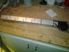
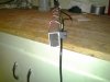
The lamp is composed of 4 x 8:1 (red:blue) 10W LEDs with matching drivers that I bought on ebay and the blower fan was purchased there too. I'm using a 20" long piece of rectangular aluminum tubing cut from a longer piece that I acquired at the local scrap yard, I think it was once part of a patio door frame, it's about 2" x 1" and has approximately 1/16" thick walls. Around 20 cuft/min of air blows through the tubing from bottom to top and I must say it runs surprisingly cool and quiet. I screwed "L" brackets on the back of the tube and onto a piece of wood strapping, screwed the strapping on the wall then mounted the light on the brackets with screws. This was built from some parts I had laying around and is a test rig, but the final design will look a lot like this and perform about the same. I'm going to build 4 of these with 5 chips and my friend is going to use them in the corners of this grow. I'm impressed by their ability to deliver intense light to almost every inter-node along the length of the plant and think I might build 4 corner lights for myself. Also, you could probably attach the blower to the tube with duct tape if you wanted to go the easy way.

Now for some pictures and in the next post a bit about the electrical end of things, what I'm using in this light and what my friend wanted for his lamps and how I would design my own corner lights. In short, I'll be discussing what would be the most economical and electrically efficient design for a lamp like this.

KEY INFO: You can use aluminum tubing like that found on patio doors to mount 10W led arrays. Just attach a 12 volt blower to one end and blow air through the tube.
 

Attachments

Last edited:

DIY-HP-LED

Well-Known Member
I just measured the temperatures of the corner lamp with an infrared thermometer gun. The bottom of the aluminum tube by the blower was 24 degrees C and the top of the tube on the LED side was 31 C, when I put my finger into the top of the tube and felt right behind the top LED, I didn't notice any extra heat. This rig runs 4 chips and each one consumes on average 6 watts of power from the driver for a total of 24 watts. Since say 20% of that energy is converted into light and shines on the plants, that leaves about 19 watts of heat. The drivers use some power (I haven't measured the total power draw of the rig yet), but since they're mounted on blobs of silicone rubber, not much of that heat is conducted to the tube. As I said, this lamp runs very cool and could easily support more 10W LEDs and a greater density of them.

The corner lamps I'm building for a friend will use 4 x 10 watt warm white LEDs and one 10W red/blue plant LED. All these LEDs run on 9-11 volts which simplifies design and increases electrical efficiency, especially when running 12VDC drivers. My friend ordered individual 10W 120 VAC drivers for each chip and I'm gonna mount these match box sized drivers on the back of the tube as I did with the prototype. This wouldn't be my first choice for a design, but it will work fine and I'm sure one of these drivers will have plenty of left over power to run the .18A blower at between 9 and 11 volts. I haven't measured the volts/amps that these chips draw (they're on the slow boat from China), but I'll bet it's no more than 8 watts and probably less. If the blower runs at say 10 volts and draws .18A that means it will draw 1.8 watts of power, there should be lots of slack. If this 10W chip's big 100W brother draws 76 watts, it's a good bet that little 10W brother uses about 7.6 watts.

I'll go into the electrical design for my own corner lamps later, but for now lets say I'd use a single more powerful 120VAC driver per lamp and run the LEDs in series/parallel arrays, this would be both more electrically efficient and cheaper.

However they are powered, 12VDC or 120VAC, the basic design of a blower and a rectangular light gauge aluminum tube will remain. I'm convinced that this basic tube design could build a lot of different LED lamp designs using 10, 20, or even 30 watt chips. From top lamps, to vertical corner lamps, to wall mounted side lamps, and even a center garden post lamp with 10 watt chips on all four sides, your only limited by you imagination. Learn to think in 3D, because with LED's it is now possible to illuminate a plant from many different angles. Try building a Fan Lamp with an HID bulb! The tubing is cheap and easy to acquire from junk yards, aluminum door shops, or bought new, blowers are only a couple of bucks and can run off the driver, or a wall wart power adapter, or the lamps 12 volt supply, if it uses one. These kind of lamps run cool and quiet and are perfect for closets, cabinets or micro grows.

I believe you could build one of these lamps easily, without drilling a hole or driving a screw (except maybe to mount the lamp). Use thermal epoxy, or self adhesive heat sink tape or pads to mount the LED chips and even the drivers to the tubing and electrical tie wraps to secure wires etc and of course the blower could be duct taped on one end of the tube. This is an easy build as far as LED lamps go.

If you use the same design as my friend and go with individual 120VAC drivers, the cost per 10W warm white chip is about $6.30US per chip driver pair, bought individuality. If you look on ebay you'll also see deals on 5 and 10 piece lots of LEDs and drivers, and if your planing your own corner lights, you'll need 20 chips/drivers and four blowers at least, so you should get a deal of some kind, like this for example 5 x 10W LEDs for $3.49US , there's all the LEDs for one lamp, or how about $20 for all the drivers That's about $25.US per 5 LED lamp, for the electrical components with the blower included .
 
Last edited:

nomofatum

Well-Known Member
Have you played with DIY thermal epoxy? I'm thinking boron nitride and/or aluminum oxide mixed with a store bought high heat epoxy. I'm going to use it for the water cooling setup.
 

DIY-HP-LED

Well-Known Member
Not yet, I understand that once you use it to adhere chips, you'll damn near have to cold chisel them off! I believe arctic silver makes a 2 part that I hear is very good. You might want to consider the aluminum sandwich held together with bolts I mentioned before and regular thermal paste. As for DIY stuff or a substitute, did you check Google?
 

nomofatum

Well-Known Member
Not yet, I understand that once you use it to adhere chips, you'll damn near have to cold chisel them off! I believe arctic silver makes a 2 part that I hear is very good. You might want to consider the aluminum sandwich held together with bolts I mentioned before and regular thermal paste. As for DIY stuff or a substitute, did you check Google?
Most common DIY is either thermal paste + epoxy or epoxy + aluminum oxide. But the better thermal compounds use more expensive and faster transmitting materials like boron nitride. I see boron nitride for making makeup as available and I see no reason it wouldn't work.
 

DIY-HP-LED

Well-Known Member
LED Street Lamp Tear Down
I was at the scrap yard the other day looking for tubing when several LED street Lamps caught my eye. I managed to get one for $15 and took it home to have a look. It was a LED Roadway Lighting Ltd (LRL) Satellite There are two types the 50 and 100 watt models. After opening one up I found the small ones were made of two 3"x5" aluminum panels of 12 3Watt 5000K cool white LEDs (25 watts X 2 panels = 50 watts), with Zener diodes on the panels to bridge defective LEDs. The larger arrays (3"x10") were made up of 48 LED arrays with the same composition as the smaller ones with each 24 LED panel divided into 2 X 12 LED arrays. The arrays will run on standard 30-36 volt, 50 or 100 watt drivers at about 36 volts, but to run them at the full 100 watts I might have to go as high as 37.5 volts on an adjustable driver.

The drivers that came with the lamps run off 120VAC and drive 2 X 12 LED arrays on the 50 watt ones. The larger 100 watt drivers are divided in two 50 watt sections for added redundancy and drive a total of 48 X 3W LEDs in four parallel arrays composed of 12 LEDs in series. All the drivers are adjustable with jumpers, are made from aerospace grade components and have first class connectors, and the 3W LED chips are top bin from HQ manufacturers. All the panels I salvaged from the lamp housings are undamaged except one, that has a chipped 3W LED. The drivers are defective and need repair, but most of the lamps, with the exception of about two, were never installed and have zero hours on the LEDs! They were unpacked and tested on the shop floor of the local utility, found defective and stored until they were disposed of, they were never returned or repaired. I found the report forms that the linemen filled out in the lamp housings describing reason for failure, "Gremlins"!

After getting one tearing it down and figuring out I could perhaps use the 1 pound of guts among the 18 pounds aluminum casting, I went back for the other half dozen and got them for 50 bucks. I stripped them down and got tons of screws and other useful items, as well as, the LED panels and drivers, it took about 20 minutes with a power screw driver to get each lamp down to a bare aluminum 15 lb housing. When I took back the housings I got $50, so the whole venture cost me $15. When I sold the housings one of the fellows who worked there said 4 more had arrived, so I went in the office and had a talk with the boss. I managed to put a $20 "deposit" on the 4 lamps and I'll get the money back when I bring in the stripped housings, so I can get the guts for these lamps for free. The components don't take up much room and I can store the drivers and LED arrays for a dozen lamps in a small card board box until I use the arrays and repair the drivers. Anyway, I've got a total of 11 LED street lamps 6 100watt and 5 50 watt including the 4 in the shop that I'll strip tomorrow.

Now for a few pictures of the tear down for those who are curious about how one of these lamps is put together and if you can use the components in a grow. In future posts I'll detail how I'm gonna make actively cooled veg lights from these 5000K cool white LED arrays using 3 or 4" wide rectangular aluminum tubing and a fan. I'm wondering if I can remove some LEDs and replace them with other spectrum 3 watt chips, they look like they are just soldered onto the contacts. If I can do this and get the drivers working, these might just give the grow a good kick in the pants, potentially 850 watts of LED light for $15 ain't a bad deal.

20150108_171617.jpg
 

Attachments

Last edited:

DIY-HP-LED

Well-Known Member
Another Stroke of Luck
I got the first of the final four street lamps stripped, it's a 100 watt model, in good condition and appeared new and unused. While I was stripping it down I noticed one of the jumpers was missing from one side of the driver, this would cause a partial failure of the lamp. Anyway, I found the jumper under the driver and replaced it, I hooked up the driver to the arrays and fired it up, the second coming was right on time! Works perfect, I figure zero hours on the driver and arrays. When they tested it before sending it out to be installed, it failed because one jumper on the driver (used to select power levels) fell off during handling. So I guess I got my $15 dollars worth with this one lamp alone. Looks like there's a veg lamp in my near future!
 

DIY-HP-LED

Well-Known Member
A Bountiful Harvest of Parts
I finished stripping the street lamps and cleaned up a bit. Here are a few pictures of some of the parts I acquired from 11 scrap 50 & 100Watt LED street lamps. The haul of things included 5000K LED arrays on 1.5 mm aluminum panels, drivers, pounds of very useful screws, electrical connectors and components like surge suppressors. A couple of the large LED panels have damaged LEDs, one has 1 with a chip out of it and the other has a couple of fairly mashed ones. I'll play with the one with the damaged chips to see how hard the LEDs are to remove. One 100 watt driver is OK and one 50 watt driver caught fire and I figure it's a write off, lots of good components on it though. I'll have to have a look at the other drivers and see if I can repair some of them.

20150111_224252.jpg 20150111_224305.jpg 20150111_224432.jpg 20150111_224518.jpg
 
Last edited:

DIY-HP-LED

Well-Known Member
A good example of why you should house drivers in metal boxes or use enclosed drivers. This 50 watt street light driver had a fried transformer that caught fire and stained the inside of the enclosure with soot. On the driver next to the multimeter, have a look at the transformer above the large silver capacitor, no problem seeing what's wrong with this driver!
20150111_224329.jpg
 

DIY-HP-LED

Well-Known Member
The Prize of the Haul
A fully working 100 watt driver and arrays with zero hours of use, like new.
20150111_224432.jpg Say hello to a new veg light. All I have to do is screw these arrays onto 3" or 4" Wide X 1" High, Foot long, pieces of aluminum tubing, drill 3" or 4" round holes (hole saw) in the center back and mount CPU fans. The fans will blow air into the center back of the tubes and out the ends, one fan per tube. This will be a design similar to the corner tube lamps and if you wanted you could mount a blower on one end of the tube, but a fan in the middle of the back of each tube is a better design, an easier build and cheaper, since the tube will be wide enough to mount a fan on.

I have to take the aluminum lamp housings back to the scrap yard tomorrow and I'm kinda hoping NOT to see any more street lamps there! Because I know I'd be tempted by the free parts and I'm getting a bit sick of stripping them.
 

Attachments

Last edited:

DIY-HP-LED

Well-Known Member
You've definitely added a bunch of ideas in the mix hp..

How did you get them working? Were they wired wrong or something?
I only tested a couple of the drivers and found 1 working that only required replacing a jumper (used to select power levels) that fell off. One other 100 watt driver has a bad side (they are divided into 2 X 50 watt sections, driven by a common dc supply) and half of the LEDs were blinking, the other side worked fine. I suspect a bad run of capacitors is the fault with most of the drivers and I'll try substituting caps first and that should fix a few of them. I have an ESR tester for components and I'll bone up on driver repair when I get the time and perhaps fix some more of them.

The lamps are divided into arrays of 12ea 3w 5000K LEDs, in series. Two arrays for a 50 watt lamp and 4 arrays for a 100 watt, the arrays run off of standard 36 volt current limiting drivers, like those I use for my other projects, though I haven't tried it yet. Next post I'll show how I go about dealing with unknown LEDs etc and how I experiment with powering them.
 
Last edited:

DIY-HP-LED

Well-Known Member
Bench testing LEDs
If you want to get into building your own LED lamps a good digital multimeter is essential for measuring voltage, current and calculating power. Another useful item that doesn't cost too much is this Digital Led 400W 10A DC Step-up constant voltage current boost Converter. It only costs about $23US and it's about the same price as a 100 watt driver, but can simulate any driver. Here is a YouTube Tutorial on how to use it, this guy has lots of interesting tutorials on related topics like driving LEDs. Here is a link to the Manual, if your interested, but English is not the first language of the author!

Your limited to 10A input, so if you power it with a 12 volt supply the output will only be 120 watts. If you power it with a 36 volt 400W regulated power supply it will operate at around 400 watts and could drive about 7 or 8 cheap Chinese 100W LEDs in a parallel array. Here I have it hooked up to one of the two 50 watt street lamp 12 LED arrays and I'm driving it at various voltages and currents. This is one of the arrays with a few hours on it, if you look closely at the orange + wire where it goes into the array connector, you'll notice that it's bleached almost yellow on one side, zero hour arrays have no wire bleaching.

20150111_224351.jpg
 

DIY-HP-LED

Well-Known Member
A couple of more YouTube reviews of the above boost converter and another 600W one. Powering them with a DC source is the main issue with using them to drive large parallel 100 watt chip arrays. You can tweak most 36 volt regulated power supplies to give up to 40 volts, but I wouldn't go higher! Some of these units can output voltage that is a lot higher than 40 volts (most have an adjusting screw), but you'll probably fry them when you put them under load.

Review: 400W Digitally Controlled DC/DC Step-Up Boost Converter - Far from Perfect

600W DC-DC Boost Converter Review and Play Around (This one's a keeper)
 

DIY-HP-LED

Well-Known Member
price seems decent for a lot of 10 48 LED LEDgine panels ($40 including shipping). Might make a great veg solution.
http://www.ebay.com/itm/LOT-Of-10-Philips-Gardco-48-LED-Panel-Ledgine-48-E324269-168V-1A-/251726351941
168 volts! Any idea what kind of driver this thing uses? Are the LED's all in series!The spectrum of the LEDs appears to be 4000K from what I could find out on Google. Yep, they might be useful as veg lighting, if you can drive them. Good price, if they're useable.
 
Last edited:

DIY-HP-LED

Well-Known Member
100 Watt 5000K Veg Tube Lamp Using Salvaged Street Lamp LED Arrays
This is a veg light constructed from three 3" x 1" x 12" (1/8 thick) rectangular aluminum tubing mounted on two 21"L x 3/4" pieces of square aluminum tubing (acquired at the scrap yard). I will be using 2 x 24 led panels mounted on the bottom of the outer tubes and 2 x 12 led panels on the center tube, that I salvaged from scrap LED street lamps. The center tube will also have a 4-1/2" x 6-1/2" x 3"H box mounted on the tube over the fan hole and will contain the fan (blowing air into the center of the tube), AC driver, 1A 12V AC fans power supply, terminal connectors and switches. The two side tubes will have fans mounted in the center like in the photos. I'll connect the tubes together using four screws and nuts per tube with a dab of epoxy on the threads. The four outside fasteners will be eye bolts instead of screws to suspend the rig from chains.

This design is based on my fan light design that used blowers to cool leds mounted on tubes. I decided to use an adjustable Chinese 3A 35V driver instead of the only working OEM driver I salvaged, because the OEM was only putting out 50W. I thought it was a 100w driver but the S48 model comes with a variety of driver options and this one was 50 watts when I got around to measuring it. The new driver will drive the 6 12 LED arrays at a a total output of 97W (35.8V X 2.71A) and each array uses 451ma of current, well below the specs which say the max drive current per array is 600ma, though I suspect it could be as high as 900 or 1000ma. At the the current I'll be driving the arrays, specs say they should produce about 95 Lm/W for a total cool white 5000K light output of 9215 Lumins

Each large LED panel is 3" x 10" and the small ones are 3" x 5" the aluminum tubes they will be mounted on are 3" x12" = 36 sq/in. Since each panel consumes about 32 watts of power and about 25% of that is turned into light and emitted that leaves about 24 watts of heat to be dissipated and say 4 watts of that radiated out the front of the arrays as heat. That leaves about 20 watts of heat for 36 sq/in of 1/8 thick air cooled aluminum tube to soak up. At .6W per square inch, I don't see an issue with overheating even if I was to drive the piss out of the arrays.

Today I purchased the tubing (about $3 a foot new) and cut the fan holes in the backs of the tubes (drill and a hole saw), siliconed on the fans temporarily until I drill the fan screw mounting holes and laid out the basic design on the bench. Tomorrow I'll, drill the fan screw holes, paint the aluminum fan tubes flat black, cut the 3/4" tubing to length, drill holes and begin assembly.

Here are a few photos to show progress so far and to give you an idea of the basic layout of the rig.

20150114_215446.jpg 20150114_215456.jpg
 
Last edited:

DIY-HP-LED

Well-Known Member
VEG Lamp Rig #1 Progress Report
The tubing cuts were made and the holes drilled, the rig was just temporarily assembled and the planning and layout finalized, then disassembled. The fan cooling tubes surfaces were painted flat black on the inside, top and sides on the outside. After applying several coats of flat black primer to the outsides, they will be set on the radiator overnight so the paint can bake hard. Next, the tubing will be reassembled, the electrical box, fans, LED panels and other hardware, mounted and the wiring can begin.
 
Top