Cooling Thoughts ...

stardustsailor

Well-Known Member
Today,I've spend a little more time than usual ,at my grow tent ....
I've noticed more closely the 'effects ' of the CXAs 3070 3000K ...
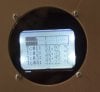
At ~ 900mA .....And with an average Tc of ~33°C ......
Then some thoughts started to pop-up to my mind ...
One after another ...
P5161351.JPG
(Pic has been 'resized' and 'sharpened' in Photoshop.)

" Well...That girl seems to really enjoy herself,ledbathing under those Warm White CoBs ..."

" at 900mA ...With Tc 33 Celcious grades ..."

" Yeap,for sure light output here ,is way different than probably in another -hypothetical situation-
where at this exact fixture ,leds would have a Tc of 80 Celcious grades,@900mA .... "

"For sure ,quite a big difference ...."

"So ,in fact two DIY same fixtures using same drivers and same leds/arrays/COBs but different
cooling approach and fan power, possibly will have way different 'effects' on plant growth and productivity .."

" Hmmm...While all the rest are the same being top-notch parts ...Cooling actually is a very crucial complicated 'part' ..."

" That can 'keep in ground' or really 'fly high up to the sky' ,a led light ..."

"it can consist of top-notch materials ....
But ...
..Without those having actually ,the ability to ensure a 100% highly efficient cooling ! "

"Not by themselves,at least ...The whole cooling design must co-operate ,with the top-notch parts ...Otherwise ...."

"Even of inferior quality parts are used ...If the cooling design is excellent ...Cooling should probably be ,evenly if not more efficient that of a system consisting of top quality parts in a bad cooling design ... "

"Ok ..But how one can measure/ determine by numbers the cooling efficiency of a design ? "

" For a given heat power disissipation ,how many "cooling " watts are used to drop x °C ? "

"Like something :

if a cooling scheme A ,dissipating 1W of heat ,using 0.5 Watts of fan power ,is decreasing Tc 10 °C
if a cooling scheme B ,dissipating 1W of heat ,using 1 Watts of fan power ,is decreasing Tc 17 °C
if a cooling scheme C ,dissipating 1W of heat ,using 0.3 Watts of fan power ,is decreasing Tc 7°C

Which is more efficient of three ? "


"Well ,it could stand not by the unit °C/Watt of thermal resistance ,but like a unitless ratio ..
Of the heat power dissipated to fan power used ,in order Tc to decrease 1°C ...."

" I'll ask for help ,at RIU ... "
 
Last edited:

Greengenes707

Well-Known Member
I like where this is going.

I'm here to learn more than participate...but I think that option 3 is the most efficient. Seems to be the least power used for the most degree lowered Tc.

Or is it a trick question of the are all the same efficiency but different application effects?
 

SupraSPL

Well-Known Member
Good line of thinking SDS. Based on the Cree temp droop chart, there is a very significant advantage to keeping a low Tj. Luckily this is something we can easily test for because it only requirres qualitative data. So we can measure the light at a given distance at each different fan configuration.

A good quality 140mm fan running at 11V only dissipates 1.2W, runs nearly silent and should be very reliable at 11V. I can use that single fan to cool a heatsink with 208W installed, so that is a very positive outcome. Cranked up to 13V it is 1.6W and at 15V it is 2.2W and still very quiet. I am not sure if cranking up the fan creates a worthwhile decrease in Tj or output, that is a very good question I will do some more testing once this heatsink is ready.

DSC07203a.jpg
 
Last edited:

Positivity

Well-Known Member
You have the perfect rig to figure out optimal fan speed/power sds

I'm sure there's a point where increasing fan speed doesn't reduce tj...where is that point?

I'd guess not far off from where we are running. I know my fan at low, medium, and high reduce heat proportionately...with high keeping it the coolest. But I doubt increasing it even further would have a dramatic tj effect...without having ridiculous fan power. At that point a bigger heatsink is on order
 

stardustsailor

Well-Known Member
I like where this is going.

I'm here to learn more than participate...but I think that option 3 is the most efficient. Seems to be the least power used for the most degree lowered Tc.

Or is it a trick question of the are all the same efficiency but different application effects?
Yes most efficient from examples is #3 ...
At your last sentence lays my query ...
 

stardustsailor

Well-Known Member
Good line of thinking SDS. Based on the Cree temp droop chart, there is a very significant advantage to keeping a low Tj. Luckily this is something we can easily test for because it only requirres qualitative data. So we can measure the light at a given distance at each different fan configuration.

A good quality 140mm fan running at 11V only dissipates 1.2W, runs nearly silent and should be very reliable at 11V. I can use that single fan to cool a heatsink with 208W installed, so that is a very positive outcome. Cranked up to 13V it is 1.6W and at 15V it is 2.2W and still very quiet. I am not sure if cranking up the fan creates a worthwhile decrease in Tj or output, that is a very good question I will do some more testing once this heatsink is ready.

View attachment 3154850
That's exactly what I'm wondering ,but not try to measure it from the light output ..
I'd preferred if Tc is used instead of light output levels ...
BTW ..Really ' cool ' fan ,this one !
 

stardustsailor

Well-Known Member
You have the perfect rig to figure out optimal fan speed/power sds

I'm sure there's a point where increasing fan speed doesn't reduce tj...where is that point?

I'd guess not far off from where we are running. I know my fan at low, medium, and high reduce heat proportionately...with high keeping it the coolest. But I doubt increasing it even further would have a dramatic tj effect...without having ridiculous fan power. At that point a bigger heatsink is on order

Exactly...
And that point is not that easy to find ...
Variables like Driving current and Ambient Temperature ,affect dramatically where that point would be ..

Yes ,a massive heatsink of course will aid in an (active) efficient cooling system.
Still ,even here, there's a 'limit' defined by 'available space' and 'weight ' ...
 
Last edited:

Positivity

Well-Known Member
One thing that crossed my mind a few times is fan placement.

The top mount works great. But at higher currents..what if you had a few of those mini low profile CPU fans blowing on the led side. With cobs..now there's room to do things like that. Can't help but think the airflow would run across the face of the heatsink and drop tj in a way the top mount can't.
 

stardustsailor

Well-Known Member
One thing that crossed my mind a few times is fan placement.

The top mount works great. But at higher currents..what if you had a few of those mini low profile CPU fans blowing on the led side. With cobs..now there's room to do things like that. Can't help but think the airflow would run across the face of the heatsink and drop tj in a way the top mount can't.
Hmmm ...
Think "gravity" and how heat (hot air / hot matter ) relates to it ..
 

stardustsailor

Well-Known Member
.....

CXA cooling.JPG

To keep Tc of the CXA close to 25 °C,is impossible with a HSF cooling system...

( Liquid Nitrogen cooling might do for the job,but this type of cooling ...
Well ...Let us just leave it 'aside ' for the time being ... )

So the whole 'game' of efficiently cooling a CXA chip is between 25 °C and 55 °C..

(Personally I 've developed lately ,a 'phycosis' with Tc max =55 °C. )

From the CXA3070 spec sheet graph ,one can notice at 1800mA driving current :

For Tc =25 °C,rel. lum .flux is >100% ....
For Tc =55 °C,rel. lum .flux is <100% ....

And the ΔRLF seems to be about 10% ...

So ...For ΔTc =30 °C (55-25 ... )
ΔRLF = 10% ...


Since it's relative ,changes to Luminus Flux due to spectral fluctuations at given drive current ,
most probably are not taken into account .


So ,with a relative 'safety' , ΔRLF ( Rel.Lum Flux difference ) can be 'translated'
to ΔP ( radiant power difference ...) ...


So...

Can we hypothesize that 'absolute cooling efficiency rate ' of CXA 3070 is
10% ΔP/ 30 ° C ΔΤC ????
Or

0.33 % per °C ?


Meaning that 'absolute cooling efficiency' of the CXA is capable of,
is 0.33 % of radiant power per 1°C ?


( Radiant power of CXA will be increasing / decreasing .33% per decreasing/increasing-respectively- 1°C
the case temperature ....


???
(For the given operating range of 25-55 °C ....)


Edit:
With a 'slight compromise' also....
That the graph lines should be taken as 'linear '..
And 'parallel' ...

Which they are not exactly ,but tend to,in both terms ...
 
Last edited:

stardustsailor

Well-Known Member
If we can ....

Then that means that cooling a CXA is a 'plan' based on a 0.33% ΔP /°C 'profit' ....
That's at least a 'starting point ' ...Some kind of ...

The next 'step' ,should be the 'balancing' of certain things ....

We 've (at least ) three numbers involved ....

-The Efficiency of the CXA per given driving Current ...
1) ΔP / ΔP ( If*Vf )

2) ΔPheat= ΔP ( If*Vf ) - ΔP

-The Power of Fans related to ΔΤc ,they can accomplish ..
3) ΔP heat / ΔP fans per ΔΤc= 1°C

And this 4) 0.33% ΔP/ΔΤc=1°C ...'absolute'.... 'profit' ...

And here starts to be complicated ....

There's a point ,that spending a certain amount of Fan power ,
keeps Tc of CXA chip at such temperature ,that the efficiency remains
at highest possible value.

Per given driving Current,of course ... ...

Spending more fan power than that,will result in lower TC case ,but
won't be adding to the 'general efficiency ,as the CXA -for the given driving Current-
won't get more efficient than a certain level/value ...

On the contrary ,more power is given to Fans ,thus 'general' efficiency is actually dropping...
A lot of power/energy , now is spend in cooling , for minimal/detrimental light power returns ...
....

Have I 'lost ' it somewhere?
Is there a 'pit' or a 'gap' ?
Something left out ?

System Cooling Efficiency can then be :

{ ΔP ( If*Vf ) - ΔP } / ΔP fans per ΔΤc= 1°C

But max absolute ΔP= 0.33% ...

{ ΔP ( If*Vf ) % -0.33% } / ΔP % fans per ΔΤc= 1°C...

The percent difference of CXA electrical power minus 0.33 % ,
divided by the percent difference of fan electrical power,
per 1°C ΔTc ,expresses the Systems cooling efficiency ...


???
 
Last edited:

stardustsailor

Well-Known Member
Example ?
dfgh.JPG


A CXA is driven at 1800mA .
Tc = 55 °C
Vf= 38.5 V .
Power of Fans used = 10 W.

New fans / other cooling system .

CXA is driven at 1800mA .
Tc = 25 °C
Vf= 38.75 V .
Power of Fans used = 30 W.

Is the +20 Watts ,worthy or not ?
The ΔP= 10% more radiant power ....

20 Watts more for +10% radiant power ..

Efficiency figure of CXA3070 at 1800mA ?
Overall fixture efficiency ?

If it was 40 Watts fan power ?

Or with just +5Watts of added fan power we had that +10% at radiant power ?

Com'on ..
Help ...
I'm not good at math,at all ...


PetFlora

Well-Known Member
Will this eventually lead to running cobs lower (bit a few more of them) to achieve passive cooling
 

happy75

Well-Known Member
Yes, with the same amount of active cooling, lower running cobs. When you take a look at the data cree provides, it states that a cob running on 25 degrees has a 17% increase on flux. Every second, minute and hour of every day. The increase of flux from 3070 Z4 to 3070 AB is just a few percent. A 17 percent increase is amazing. Also almost impossible to reach without large initial investments.

relative flux vs temperature.JPG

In the same pdf cree gives examples what the effects are when a heatsink has a different orientation. If the data are right (and I interpret it good), it makes a lot off difference.

thermal impact orientation heatsinks.JPG
 

stardustsailor

Well-Known Member
Yes ...
Now ,I 've finished the 'burn-in ' time of my new CXA fixture ...
Doing some last "mods " ..

Here some notes of mine about the CXA 3070 array ...
z4 thermal.JPG

cxa heatsink sim #2.jpg

ab thermal.JPG


Equation 1: Thermal power calculation

Pt= (1-e) * Vf * If

where:
Pt is the thermal power (W)
e is the Radiometric efficiency of the LED (% / 100 )
Vf is the forward voltage of the LED (V)
If is the source current to the LED (A)

Equation 2: Fourier’s law of heat conduction

Qcond = -k *A* (ΔΤ/Δx )

where:
Qcond is the amount of heat transferred through conduction (W)
k is the thermal conductivity of the material (W/m K)
A is the cross sectional area of the material through which the heat flows (m2)
ΔT is the temperature gradient across the material (°C)
Δx is the distance for the heat must travel (m)

Equation 3: Newton’s law of cooling (convection)

Qconv = h *A *ΔT

where:
Qconv is the amount of heat transferred through convection (W)
h is the heat transfer coefficient (W/m2K)
A is the surface area (m2)
ΔT is the temperature gradient across the material (°C), typically the difference between the surface temperature and ambient air temperature

Equation 4: Radiative heat transfer equation

Qrad = ε σ A (Ts^4- Tf^4)

where:

Qrad is the amount of heat transferred through radiation (W)
ε is the emissivity of the surface (dimensionless)
σ is the Stefan-Boltzmann constant (5.67 x 10⁻⁸ W/m2K4)
A is the surface area (m2)
Ts is the surface temperature of the material (°C)
Tf is the fluid temperature of the medium (°C), typically referenced to the ambient air temperature


-----------------------------------------------------------------------------------------------------------------------
For CXA3070, LER=325 ....

Le (lm/W )= e (% ) * LER ( lm/W) =>
e = Le / LER
http://apps1.eere.energy.gov/buildings/publications/pdfs/ssl/ohno_color_raleigh2010.pdf

Equation 1 for CXA3070 becomes :

Pt= (1-(Le/LER)) * Vf * If

.......................................................................................................................................................

Thermal Path of CXA3070
:

Tj => R j-c => Tc => Rtim + Rheatsink => Ta

----------------------------------------------------------------------------------------------------------------------

CXA3070 R j-c = 0.8 C/W

Tj = Tc + ( R j-c * Pt ) =>

Tj CXA3070 = Tc + ( 0.8 * (1-(Le/325) ) * Vf * If )
---------------------------------------------------------------------------------

Tc = Ta + { ( Rtim + Rheatsink ) *( (1-(Le/325) ) * Vf * If ) }

Rtim (from Equation #2 ) = d / ( k* S )

where:
Rtim is the thermal resistance of TIM layer (C/W)
k is the thermal conductivity of the TIM (W/m K)
d is the thickness of TIM layer (m)
S is the surface area of TIM layer (m^2 )

Rheatsink (From Equations #3 & #4 )= ΔΤ / ( Qconv + Qrad )

.............................................................................................................................................

Heatsinks used :

Rheatsink-passive = 0.6 C/W (natural convecting at 200mm length )
heatsink.JPG

and with forced convection (with Fans used , at max =~2.84m^3/min )

Rheatsink-active=0.09 C/W
forced.JPG


Rtim = 0.00005 / ( 10 *0.00075 ) = 0.0067 C/W

( d=0.05mm ,K=10W/m K,S= 27.35mm *27.35 mm )

Rtim+ R Rheatsink-active= 0.0966 C/W = 0.1 C/W

For Io= 2100 mA ....(Bin z4,TC=55 C )....
Vf =39.23 V
Le =102.57 lm/W ....

Fot Ta =25°C ....

Tc = Ta + ( 0.1 C/W * (1-(102.57/325) ) * 39.23 * 2.1 ) =>

Tc = Ta + 5.638 °C !!!

Tj = Tc + ( 0.8 * (1-(102.57/325) ) * 39.23 * 2.1) =>

Tj =Tc + 45,106 ...


Tj =Ta + 50,744 °C

For the fixture ,at Io= 2100 mA and Fan power at max ...
 
Last edited:

stardustsailor

Well-Known Member
Max Tc =45°C (Ta=26°C ) for Io = 2070mA ...
At lowest fan speed setting !
:hump::hump::hump::clap::clap::clap::hump::hump::hump:
I'm pretty satisfied with the cooling of the fixture ...
:bigjoint::bigjoint::bigjoint:
P5301385.JPG

(Did some super-finishing on the heatsinks and applied a new thermal paste ..
Way-way expensive one ..:finger::wall::cuss:

.Fischer Electronik WLPK ...
thermal conductivity: 10 W/m·K...
at about 0.05 mm layer (with use of stencil )...
http://www.fischerelektronik.de/web_fischer/en_GB/heatsinks/E01.08/Thermal transfer compound and thermal interface film/PR/WLPK03/index.xhtml )

Changed the MCU software ,a bit ..

-Thermal Protection Limit is increased @ 62°C ...Summer can get pretty hot here ..(>40°C )

-Bar-graph thermometer ,proves to be way more useful and practical ,than showing the 'average Tc temperature' ...
(20°C -30°C - 40°C -50°C -62°C...Appendix...LOL! )

:dunce::dunce::dunce:
P5301388.JPG

Cheers!
:peace:
 

Positivity

Well-Known Member
So when can we pick up the official custom arduino and thermocouples with 8 inputs?

Don't need no stinking lightning mode...we need cxa thermal monitors! Maybe a 730nm timer that can run 10-15w..light timer...and UVB floro timer.

I'm be all in to that!! Then again I might not want to know what each one is running at..lol

Nice work..:bigjoint:
 
Top