justsmokedope
Well-Known Member
Decided to attempt a 3d Printed undercurrent Hydroponics system (UC RDWC) , as they are very good systems but just cost a stupid amount of money. It seems that things like the large tank connectors realy drive to cost up.
i also seem to have collected a lot of filament that i can use to print most parts except the 110mm pipes and the quality square buckets i found.
PETG fillement costs about £15/16 for 1kg and can print 2-3 massive fittings for that if not more.
im printing :
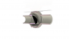
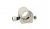
110mm/111mm tank conectors threded with tpu seal
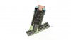
110/111mm reducing tee with 1inch bsp threaed with extra drain hole for drain and cleaning the system
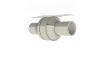
1inch bsp filter and filter incerts
a filter extender
net pots
110mm/111mm equal tee solvent weald
110mm/111mm equal tee threaded
110mm/111mm blanks for end
110mm pipe filter / catcher
A venturi jet pump willrun the whole system hopfully , the air is used to move water around the system while also adding dissolved air into the water. one air pump reduces the running costs. currently 110mm but might reduce down to 1inch pipe also but a work in progress as figured larger pipe might help with flow.
i also seem to have collected a lot of filament that i can use to print most parts except the 110mm pipes and the quality square buckets i found.
PETG fillement costs about £15/16 for 1kg and can print 2-3 massive fittings for that if not more.
im printing :
110mm/111mm tank conectors threded with tpu seal
110/111mm reducing tee with 1inch bsp threaed with extra drain hole for drain and cleaning the system
1inch bsp filter and filter incerts
a filter extender
net pots
110mm/111mm equal tee solvent weald
110mm/111mm equal tee threaded
110mm/111mm blanks for end
110mm pipe filter / catcher
A venturi jet pump willrun the whole system hopfully , the air is used to move water around the system while also adding dissolved air into the water. one air pump reduces the running costs. currently 110mm but might reduce down to 1inch pipe also but a work in progress as figured larger pipe might help with flow.
Attachments
-
 110 t with bsd 1inch and drain plugv3 v5.jpg51.5 KB · Views: 40
 -
 110mm tank conector blank top thred v1.png175 KB · Views: 45
 -
 110mm tank conector 3d print-0.5 ajust2edd v4.jpg57.8 KB · Views: 39
 -
 110mm tank TEE threadsb v2b.jpg55.3 KB · Views: 41
 -
 filter 2 v4.jpg79.2 KB · Views: 38
 -
 filter 2 v4b.jpg45.5 KB · Views: 40
 -
 110mm pipe filter v4.jpg61.5 KB · Views: 37
 -
 111mm tee v4.jpg49.2 KB · Views: 36
 -
 jet pump2 v6.jpg60.5 KB · Views: 36
 -
 jet pump2 v6.png126.2 KB · Views: 35