Offering tech support

automated

Active Member
Hi there fellow RIU’s.

With the enormous amount of information I have been reading from RIU I figured I might try and return the favor by offering some assistance when it comes to applying technology for digital data logging, mobile monitoring and automated control and will lend insight and ideas to try and help think up or work out solutions with tech and hardware relating to growing.

From small appliances (like my climate control from my journal) to large networked setups; I have build the hardware and software for huge power controlled systems to monitor and control literally 1000s of power sockets and sensors at the same time. (data center power management)

I build web interfaces with secured connections with the help of php web applications and mysql database back-ends.
I have lots of experience working with web interfaced hardware thinking up approaches and working out techniques to support countless of computer connected devices to control and monitor them. (R&D)

I have a keen insight into seeing how stuff works; I can look at a piece of tech and can see how some of the smallest components work and operate, making me able to work out adaptions and or improvements. (if I dont understand something I generally figure it out in no time with doign a little research)

With an eye on low budgets I’m also able to apply uncommon used materials and techniques for results desired where most would not have thought of; keeping costs low.

If you have questions or looking for a second opinion then feel free drop a line and see where it might get you.
I cannot promise a solution, but your free to try, as will be the replies given.


bongsmilie
 

MrFowlio

Active Member
Here's a wiring question :)
My ballast has 5 ports, tried wiring it up with the ignitor and the capacitor but all the solutions say I need to connect the two COM wires to the capacitor but my ballast coil is closed. Here is a picture, it's helluva confusing and ANY help would be appreciated. My input is 220v (I'm in South Africa) and I'm trying to run a 400w hps off this ballast. The com wires are confusing (can't see the short and long side) and I'm still unsure where to place the capacitor on my circuit.

Thanks again in advance!!!!

here is the picture of my ballast and the ignitor. I know that "z" or port "d" is "x3" in the wiring diagram I got off the internet (attached here) but need advice for the rest....
HPSwire.gifIMG_0262[1].jpgIMG_0260[1].jpg


One love and happy toking!

Fowlio
 

automated

Active Member
I took the liberty too look up the details of the ignitor, says here its a pulse based one.
From this site i got the next following diagram for pulse based ignitors with your ballast.

aansluitschemapulse.jpg

Pretty self explenatory, you should have the capacitor too.

Hope you can use it :)
 

Mechanical

Well-Known Member
Here is one for you..
What would it take to hook up a few of those garage door lasers (the ones that stop the door from smashing someone) to some kind of slow moving but powerful motor? I would like to have it set up to raise the lights when the laser is broken by a leaf or a bud and stop when it connects again. That way I could mount the lasers on the side of my light about 6" down and never have to worry about raising them again.
 

contraptionated

New Member
Won't work. That motion sensor simply gets the motor to go in reverse until the door presses down on a limit switch which tells the motor to stop (because it is now fully open) and then try to close again when the infrared is unbroken. To make it work you would require a different control system that isn't used on a garage or elevator door.
 

Mechanical

Well-Known Member
Won't work. That motion sensor simply gets the motor to go in reverse until the door presses down on a limit switch which tells the motor to stop (because it is now fully open) and then try to close again when the infrared is unbroken. To make it work you would require a different control system that isn't used on a garage or elevator door.
Ya I understand that.. What I was asking is what would I need to do to get it to function the way I need it to? Would it be as simple as soldering some pieces together or would it be chips and shit? I don't know much about this kind of thing but I love DIY:) I know it would take some tinkering. It would be complicated for sure!!
 

automated

Active Member
I have been toying with a similair idea.

Your approach.

Using a laser you need to interupt the signal in order to detect an interference.
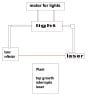
You would get a situation where your laser and reflector would be attached to your light hanging under it, lasering horizontal over the canopy.
If a plants grows too high, the beam gets interrupted, and it should give a signal so the lights move up.

Downside is that you would generally only have 1 laser with only a very narrow beam.
If plants left or right of the beam should grow past the beam, they would grow close to the light and could burn.
Having more lasers could indeed solve this.

laser.jpg


The hookup would need a manual adaption of the circutry, seeing as you want to have more signals able to indicate the lights need to go up.
Next to that, you would also require a system to get it back down.
Just imagine if you would accidently move your hand through the beam and it would go up.
I am not sure if you should use the laser idea to also get it back down, I can see some issues with the lights moving up and down a bit spastic as an oscilating fan could blow the leafs back and forth between the laser.
A solution could be to check plants height with the lasers once or twice per day.

So there are few approaches to this.


If you look at it component based, you would get something like:

Powered Laser component: will give a voltage signal when interreputed. (ouput)

Powered Motor circutry connected to laser and motor: rerceives Voltage signal (input) indicating motor movement required until signal goes off.


I would also have/add the manual buttons to make them go up or down, for sake of convenience.

Do you have some hardware laying about ?


Won't work. That motion sensor simply gets the motor to go in reverse until the door presses down on a limit switch which tells the motor to stop (because it is now fully open) and then try to close again when the infrared is unbroken. To make it work you would require a different control system that isn't used on a garage or elevator door.

Certain existing functions can often easily be disabled.


I have been thinking of these: ultrasonic distance sensors.
You have lots of these things, like parking sensors for cars, or even smaller DIY systems for hobbyists called ultrasonic range finders and ultrasonic range detection.
They will require something like an arduino or other atmel based chip board to read the values and relay signals.


ultrasonic.jpg
 

Mechanical

Well-Known Member
I have been toying with a similair idea.

Your approach.

Using a laser you need to interupt the signal in order to detect an interference.
You would get a situation where your laser and reflector would be attached to your light hanging under it, lasering horizontal over the canopy.
If a plants grows too high, the beam gets interrupted, and it should give a signal so the lights move up.

Downside is that you would generally only have 1 laser with only a very narrow beam.
If plants left or right of the beam should grow past the beam, they would grow close to the light and could burn.
Having more lasers could indeed solve this.

View attachment 2662661


The hookup would need a manual adaption of the circutry, seeing as you want to have more signals able to indicate the lights need to go up.
Next to that, you would also require a system to get it back down.
Just imagine if you would accidently move your hand through the beam and it would go up.
I am not sure if you should use the laser idea to also get it back down, I can see some issues with the lights moving up and down a bit spastic as an oscilating fan could blow the leafs back and forth between the laser.
A solution could be to check plants height with the lasers once or twice per day.

So there are few approaches to this.


If you look at it component based, you would get something like:

Powered Laser component: will give a voltage signal when interreputed. (ouput)

Powered Motor circutry connected to laser and motor: rerceives Voltage signal (input) indicating motor movement required until signal goes off.


I would also have/add the manual buttons to make them go up or down, for sake of convenience.

Do you have some hardware laying about ?


Won't work. That motion sensor simply gets the motor to go in reverse until the door presses down on a limit switch which tells the motor to stop (because it is now fully open) and then try to close again when the infrared is unbroken. To make it work you would require a different control system that isn't used on a garage or elevator door.

Certain existing functions can often easily be disabled.


I have been thinking of these: ultrasonic distance sensors.
You have lots of these things, like parking sensors for cars, or even smaller DIY systems for hobbyists called ultrasonic range finders and ultrasonic range detection.
They will require something like an arduino or other atmel based chip board to read the values and relay signals.


View attachment 2662662
I would start from scratch and it would be a learning project. I don't think I have anything I could use right now. I love learning new shit though.. Ill have to look into the ultrasonic range finders.. Do you think its doable for a person without a lot of knowledge about circuitry to do?
 

automated

Active Member
There is tons of material out there with tutorials and schematics.

To keep it simple, if you have a little investment for it, invest in one of those mini computers.
I used a raspberry pi as its a complete computer, but an arduino system would be perfect for such a project. (small and much simpler to get started)

Arduino has lots of development boards/packages with simple instructions and ready to used scripts. example of 80 bucks one
If you start out, its handy to have a breadboard and some wiring.
These boards go from anywhere from a 30 bucks to 150 varying in whats in it extra.

After you test build an initial setup, you can hardware it and use it.

Here is a site with arduino related info

I recently got an arduino nano, small device with several pins for inputs and outputs for my Co2 sensor and servo for valve control.
You can get arduinos which are a bit bigger that can bear shields on top of them,
but I would go for a smaller device like the nano, and simply hookup existing components which are as simple as wiring up two or three wires.

With the functionality from the light control, you could get all the things (buttons and a couple of sensors and relais control) working on a nano.

You tube lots of video about these things too (also with range finders).

And the software from arduino has a really simple interface with lots of stuff already in it.


Good luck, and if you need any help, just drop a line :)
 

blacksun

New Member
Having the laser and it's reflector directly connected/tied to the light+motor would raise the laser+reflector just as much as it raises the light+motor.

No need for that distance sensor craziness.

K.I.S.S.
 

automated

Active Member
Having the laser and it's reflector directly connected/tied to the light+motor would raise the laser+reflector just as much as it raises the light+motor.

No need for that distance sensor craziness.

K.I.S.S.
Yes, if you had read the post you would have seen it stated that too. (I wouldnt haul the motor up and down though >_> )
And that the ultrasonic distance sensors is just another option for detection instead of the lasers.
 

MrFowlio

Active Member
I wired my transformer, capacitor and ignitor exactly to that in the picture, even changed the live and neutral around on the bulb holder, still no light although the ballast does hum slightly. Checked and double checked all connections, especially the one done up with red insulation tape. My ballast does say that it has port (Z) for a superimposed ignitor and mine is pulse ignitor, it shouldn't make a difference surely? What are your suggestions dude? Here is a picture of the wiring, and thanks so much for the help!

One love

IMG_0267[1].jpg
 

MrFowlio

Active Member
The only problem I can think of is that I need a superimposed ignitor instead of a pulse ignitor? I'm really baffled dude...
Any suggestions etc would be highly appreciated :weed:
 

automated

Active Member
Check the ignitor closely.
the schematic was for your ballast, you have a different ignitor.

The black and red needed to be switched :)


I edited the image and placed your ignitor in with an simple solution
Image2.jpg
 

MrFowlio

Active Member
I have wired the ballast like that from the beginning, just look at the picture I sent more closely and you will see that the black wire connects to terminal "D" on the ignitor and the live wires are fine too. (sorry I'm having a giggle because your solution takes place in the picture I took) :) :) The transformer says it's for a superimposed ignitor, but I have wired it according to your solution :)
Here is the picture of the info on the transformer (ballast) :)

"Z" on the transformer is wired to "D" on the ignitor...
IMG_0272[1].jpg
 

automated

Active Member
I should have read the rest of the details from the ballast better.
In the beginning I did a search for the model details of your ballast, and found several schematics with both ignitors.
The one I showed simply had the best looking overview.

I must apologise, because this is a rather dumb mistake, your ballast says you need the superimposed one.
So you will need the superimpossed ignitor.

How did you end up with the pulse ignitor ?
 

DONNYS

New Member
I took the liberty too look up the details of the ignitor, says here its a pulse based one.
From this site i got the next following diagram for pulse based ignitors with your ballast.

View attachment 2662011

Pretty self explenatory, you should have the capacitor too.

Hope you can use it :)
i didnt read whole thread see if got answer but sounds like u got a multi tap unit
if u dont have figured out i can walk u throu it
 

automated

Active Member
i didnt read whole thread see if got answer but sounds like u got a multi tap unit
if u dont have figured out i can walk u throu it
MrFowlio required the schematics to hook up his ballast, turns out his ballast only supports the superimposed ignitor, or so it seems.


Here's a good place to start. http://www.aboutplcs.com/click/

They are cheap and if you can read carefully you can control your whole grow.

side note: Banner makes photo emitters and receivers that will last a lifetime as long as you don't step on them.:lol:
Thats actually pretty good stuff.
Thanks for the link.
 

DONNYS

New Member
MrFowlio required the schematics to hook up his ballast, turns out his ballast only supports the superimposed ignitor, or so it seems.


Thats actually pretty good stuff.
Thanks for the link.
did udid u get it figured out ?
if not i got u covered
i been in school for yrs for electronics
get it figured out ?
 
Top